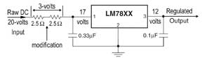
Figure 1: The filament power supply modification applied to the Jackson guitar amp
Everyone’s energy-conscious these days, so turning gear off when it’s not in use saves on the electricity bill and helps keep your toys healthy. To further promote equipment longevity, find the major heat sources in your rack, and add space above/below to improve ventilation.
Broken gear that’s on 24/7 often has an obvious hot spot inside where you can’t see. In a well-designed circuit, components can warm to the touch — with the lid off — but shouldn’t cause first-degree burns. A short-term cure is to replace the damaged component; better still, fix the problem.
Let’s look at an early production run of a Drawmer 1960 stereo comp/limiter and a Jackson Apogee 50 guitar amp — two very different pieces of gear with similar problems. Both have four tubes of the 12A?7 dual-triode variety (where “?” is the wild card for T, U, V, X, Y or Z). Clean, quiet DC power is supplied to the tubes from an LM7812 voltage regulator rated at one amp. Four 12-volt filaments in parallel consume 600 milliamps (mA) of current. This is close to 75 percent of the 7812’s “safe” capacity, which would be fine; however, tubes draw much more current when cold.
If you’re hip to Ohm’s Law (I = E/R, R = E/I) you can see that one 12V filament (or heater) consuming 150 mA has an equivalent hot resistance of 80 ohms. I measured about 15 ohms cold, so the startup current for one tube is about 800 mA (1,000 mA = 1 amp). That multiplied by four momentarily exceeds the LM7812’s capacity, considerably decreasing its Mean Time Before Failure (MTBF). It was no surprise to find a normally green circuit board turned brown from heat.
The Jackson Story
Voltage regulators need a few extra “raw” volts at their input so that their output can be constant — even if the AC at the outlet is shy of its 115V~125V window. On the Jackson, 20V of raw DC fed the regulator, which is within tolerance if the load is a half-amp (500 mA). With no internal ventilation to allow the heat sink to do its job, the 7812 got hot enough to eventually discolor the board and even melt the solder before failing entirely.
With no schematic, limited access to the PCB’s underside and a student audience, I opted for expediency — cutting the regulator’s legs and de-soldering the remaining bits from the top. The regulator was relocated to the back panel, providing more surface area and “outside world” ventilation to facilitate heat dissipation.
Next, I inserted a resistor in series between the raw power supply and the regulator to reduce the 8V input/output differential to 5 volts. This same resistor would also limit the total current on power-up by taking the hit — allowing a greater voltage drop — so that the regulator wasn’t strained on awakening. This is a simple, passive version of a current source, taking advantage of the fact that the resistor’s value would increase with heat. I used a variation of Ohm’s Law to calculate the resistor value based on the current required by four parallel filaments; I picked the voltage dropout of the air: It’s R = E/I, where 3 volts/0.6 amps = 5 ohms. (See Fig. 1.)
Next, the Power formula determined the power (in watts) dissipated by the resistor; the wattage divided by 0.75 ensures that the resistor operates in a comfortable operating zone. P = IE = (0.6 amps × 3 volts) = 1.8 watts/0.75 = 2.4 watts. Remember, this is based on post-warm-up operation. A trip to the local surplus store yielded two exquisite 2.5-ohm resistors (rated at 5W each) to be wired in series. Post-mod, none of the components was more than warm to the touch, and the amplifier is alive and well.
Sharing the Drawmer’s Load
Interestingly enough, the Drawmer 1960 had a fuse on the filament circuit to protect both the power transformer and the tubes should the regulator fail. Not only was the LM7812’s heat sink inadequate, it was inside the unit with four vacuum tubes, plus other overly hot regulators. No amount of top panel ventilation holes would suffice, especially as the 1960 would likely be sandwiched between two pieces of gear. The 1960 was eventually reborn as the 1969 — sonically tweaked and redesigned for greater reliability.
Note: Tube-era designers concerned about heat literally thought outside of the box by mounting tubes (and later transistors and heat sinks) where ventilation was easiest to come by.
To improve heat management in the 1960, I chose a more elaborate “active” current source: a power transistor for each tube. Even better than the single resistor added to the Jackson amp, the transistor current source allows the filaments to draw only 150 mA, even during power-up. The tubes would take longer to warm up, with the added benefit of extending life. Each transistor had its own piece of chassis real estate and was barely warm compared to the concentrated heat of the single 7812 regulator. (See Fig. 2.)
Currently Speaking
The current source has been around for a long time. One example goes back to the vacuum-tube era — the LA-2A output stage. I was first aware of it in the channel assignment section of MCI consoles, where driving all the LEDs in series required far less power than in parallel. I also found it more recently in aftermarket replacement power supplies for tube microphones.
Eddie Ciletti’s kitchen is at tangible-technology.com, where the motto is, “If you can’t stand the heat, get out the soldering iron and modify, modify, modify.”
AUDIO SCIENCE
Tube Filaments Explained
Common to audio gear, dual triodes — such as the 12AT7, 12AU7, 12AX7, 12AY7 and 12AZ7 — have two separate amplifiers. “Triode” refers to the three principal components: cathode, grid and plate. In a vacuum tube, the filament boils electrons off the cathode. These negatively charged particles are attracted to the opposite charge — in this case, the plate, which becomes positive when a high voltage is applied. Each amplifier within the dual triode has its own filament, and in the 12A?7 family the two filaments can be wired in series as a 12.6V tube (150 mA) or in parallel as a 6.3V tube (300 mA). Back in the day, an AC voltage was applied to the filaments. However, in many high-gain applications, our heightened sensitivity to noise requires clean, filtered DC, hence the use of regulators.
— Eddie Ciletti