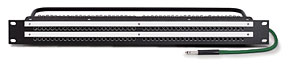
This TT patchbay packs 96 jacks into a single rackspace, yet this mode. terminates in raw contacts, ready for 288 solder connections on the rear side for installation.
In any installation, the fundamentals are the same: Wiring may be the most obvious factor, but it’s just one consideration. First and foremost, when you’re wiring a studio, create a list of things to do, as well as a labor and materials estimate. Also, realize that if your budget’s tight right now, you can postpone part of a project, making provisions for later expansion.
Don’t ignore professional advice, whether free or for hire — weigh it carefully. No matter how much of the future has been provided for in your plan, conventional wisdom still applies: Don’t change horses midstream. Develop a relationship with your designer(s) early enough to know you’ve got a good fit. Too many cooks spoil the broth. There are many ways to implement ground in an audio system, but only one concept at a time, please. And, of course, there’s Murphy’s Law. So be prepared with backup or alternative gear and plans.
Last, but not least, don’t forget the fudge factor: Nothing ever costs exactly what you think it will. The actual multiplier is determined by the thoroughness of the first estimate. However, with Net access, you’ve got no excuses not to do research. Take your punch list to the Web and run with it. But let’s start with the non-wiring details.
Speaking of Mr. Murphy, there are three “gotcha” issues — power and cable distribution is one, followed by priorities like HVAC (Heating/Venting/Air Conditioning) and cable conduit size. Power and audio wiring paths should intersect rather than run parallel — or be very far apart for the shortest possible distance if they must take a similar path. HVAC must be able to deliver cooling, both to the obvious creature zones and to equipment closets. Often overlooked, exhaust is as important as the ability to deliver cooling. Any ductwork should be oversized to allow for the quiet delivery of necessary control room and studio cooling.
SURPRISE!
Strange as it may seem, audio consoles and support equipment are impulse buys for some and after-the-fact whims for others. The proud purchaser will hand over the prize to those who must do the dirty work. Even worse are the surprises on the first install day, when wiring troughs or conduit are undersized or nonexistent, and the console has been swapped out for one that was “a better deal.” If you can’t do it, then pay someone to oversee every step of the design process.

Figure 1: Pin-out for the 8-channel, 25-pin D-sub audio conector in the Tascam standard. Three pins are used for balanced lines.
THE OCTOPUS’ GARDEN
For some studios, the patchbay that came with the console is the center of the universe. Conscientious installers will integrate changes — gear additions and subtractions, or facility expansion — according to the manufacturer’s layout scheme. It’s often difficult to match the density that production manufacturing can achieve; practice does lead toward perfection.
However, when a patchbay is designed as an independent entity, it becomes a challenge to lay a foundation for future expansion. Translation: You only have to hardwire one patchbay (or have it done) to know that modular is the way to go.
After the initial investment of building or buying a modular patchbay, everything down the line is so much easier. This eliminates the Medusa aspect of patchbay fabrication; the job of snake-charming multiple, lengthy snakes can be done off-site. Modular bays allow both the customer and the installer to make changes, upgrades and mistakes without the traumatic behind-the-bay surgery.
You can buy pre-made modular patchbays with your multipin connector of choice — Elco/EDAC, DB-25 and DL are the most common. Most multipin connectors come in crimped and soldered versions. Crimped connections are easier and just as reliable as soldered if they’re done correctly. Originally intended for computer applications, DB-25 (D-Sub) connectors were first popularized for audio use by Tascam and are now used by dozens of manufacturers. Figure 1 shows the pin-out of this “Tascam standard,” where three pins are used for balanced line (hot, common and ground) connections for each of the eight channels. Pin 13 is unused.
D.I.Y. MULTIPIN
Let’s assume you’ve purchased a modular patchbay and are planning to do the rest of the wiring yourself. If crimping, the one caveat is that you must choose the correct wire gauge (diameter) to ensure a snug physical connection and long-term reliability. (Consult the dealer for the recommended gauge before ordering the cable.) You’ll be investing in an Elco/EDAC crimp tool (about $200 street) and crimp pins ($0.20 each). A 90-pin male or female connector and metal hood housing set is priced around $35. Speaking of the connector hood, don’t forget to slide the housing onto the cable before you start soldering or crimping. There is nothing worse than completing multipin snake connections and then realizing that the cover is still sitting on the workbench.
PATCHBAY PREFERENCES
I have no patchbay connector preference — traditional telephone-style ¼-inch or Tiny Telephone (TT) Bantam — except that the latter allows more density, and for many customers, space does seem to be at a premium. What makes these professional bays last for so long is contact pressure. The jack and its normals are self-cleaned with each insertion. It’s the plugs that get funky, but more on that in a moment.
Patchbays to avoid are the type most often found on low-cost consoles. These dreaded circuit board — mounted jacks are more plastic than metal — they simply don’t hold up because of insufficient contact material and the lack of self-cleaning pressure. I recommend wholesale replacement/upgrade.
In between the dreaded and the traditional are the D.I.Y. bays with standard ¼-inch (or RCA) connectors on front and back. At first, these seem cost-effective, but they can cost about as much per jack as a nonwired pro bay. If you use them in hostile/humid environments, then periodically clean both the patch plugs and the rear plugs. Be sure to strain-relief the rear-entry cables to ensure that the plugs are not accidentally pulled out of the jacks if activity occurs behind the rack.
ROUTINE MAINTENANCE
I really want to encourage patchbay awareness so that drastic maintenance is not necessary. My own bays have been in service for about 15 years and are still going strong.
For traditional patchbay preventive maintenance, I recommend polishing the patch cords and wiping off polish residue with a cloth soaked in denatured or 99-percent alcohol. (A cloth with a “taste” of contact preservative can also be used, but sparingly; be sure to use a separate cloth to remove the excess.) Brass plugs are better at showing you they need attention; the nickel-plated plugs may need less attention, but they can hide the nonconductive films that build up from handling and environmental “corrosion.”
Please do not spray patchbays with contact cleaner — a burnishing tool is much more effective at polishing all the contact points except the normals. Don’t leave patch cords in the bay for long periods of time because exposure to “the elements” can degrade the normals. Exercising the bay — by plugging and unplugging patch cords — can bring normaled connections back to life. When that doesn’t work, remove the individual jacks to burnish the contacts from the side.
DIGITAL PATCHBAYS
Digital audio gear is more likely to be electronically patched (like analog video) rather than via mechanical patchbay. Digital routers come in all flavors and sizes, and there are more devices with digital I/O from the conventional “outboard” to microphones and keyboards.
One of my sound design clients solved his minimal patching needs with a Digidesign 192 with two digital I/O cards. His assortment of digital outboard gear includes a Quantec Yardstick, Lexicon PCM91, Eventide Eclipse, TC Electronic Reverb 4000, Focusrite ISA 428 mic pre, and converters by Lucid and Lavry. All devices are hooked up via AES. Inputs are switched within the Pro Tools hardware setup dialog (set 1 through 8 is for recording, set 9 through 16 is for mixing).
HOT, HOT, HOT
Heat is the enemy of electronic devices — analog and digital alike — and when developing your studio wiring scheme, consider the need to accommodate the placement of gear that can be remotely operated (such as CPUs) in more distant locations. Hardware routers, servers and workstations all get hot. Gigahertz CPUs, whirring hard drives and the fans to keep everything cool typically operate without filters. Heat affects processing ability, so a machine room is a good location for gear that’s noisy and in need of cool, clean, filtered air. I often reverse fans, add filters and more fans to gear that can easily be modified.
Because laptops are often part of the equation, pay attention to models with obvious air intake and exhaust. Especially when either is on the underside, the worksurface must be on a hard, non-cushy surface. Traditional desktop models should also be situated in well-ventilated areas. If somewhat out-of-sight, then check the intake and exhaust grilles for fur balls and make a point to vacuum regularly. (Don’t forget to change the filters — vacuum or otherwise — to ensure optimum performance and airflow.)
Tube gear, particularly the modern retro variety, tries to compete with the iPod generation by packing more processing into smaller spaces. Think of the generous amount of real estate designed into the packaging of an LA-2 limiter, Fairchild compressor, Pultec EQ or RCA preamp modules. In those days, the tubes were mounted outside on the rear of the unit. Modern iterations squeeze a pair of channels into a 2U package, with tubes on the inside.
If you love your retro gear and want it to last more than a one-night stand, then be considerate and leave air space between each unit — especially if you happen to notice that the top and bottom panels have screens or have ventilation holes. These tips are borne from the service bench — I see what happens when gear is stuffed into racks without regard for temperature. Think more like a geek — you’re not packing a truck — and if empty rackspaces are not part of your aesthetic, then buy 1U rack screens.
CHICKEN OR EGG?
Recording system installation requires a skill set that can only be acquired with experience, especially in terms of what can go wrong. Don’t get overwhelmed: Post-install problems help us do a better job. Good luck!
Eddie Ciletti would like to thank the electron goddess for inspiration and guidance and Tom Hambleton of
www.undertonemusic.com
for the digital outboard list.
PATCHBAY AND GROUNDING OPTIONS
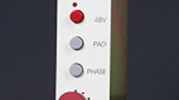
There are several ways to implement a ground distribution in an audio system. Some patchbays, like the Audio Accessories model pictured, have options that could first be used for interrogation (chasing a ground-related hum or buzz) and then be “locked in” for final implementation.
The WDBP-9615-SH ($890) is a 2×48×1.5RU prewired patchbay to DB-25 connectors. This unit has switches on the rear to configure the normals and grounds on a per-jack basis. Its ground options include:
Grounds Not Bused: All jacks are isolated and each independent ground is brought out to rear termination.
Grounds Bused: All jacks are bused together, making a common ground. This common ground is then routed to a binding post at the rear of the panel.
Grounds Vertically Strapped: The grounds of each vertical jack-pair are connected. Horizontally, the grounds of these vertical jack-pairings are still isolated. This lets the user maintain a solid ground path from source to destination for each vertical pair of jacks.
Grounded to Specific Application: If you need one row bused and the other not, or have another method you need implemented, the unit can be customized to meet specific requirements.