You can warn a child not to touch a hot stove, but until the kidchars a finger or two, the concept of getting burned usually remainsjust that, a concept. For some of us, the same principle applies toaudio concepts. Until we’ve seen–or better yet, made–the connectionsourselves, textbook how-to’s often go in one ear and out the other.That’s why, when I set out to expand and reconfigure my patch bayrecently, I first investigated the ins and outs of a few up-and-runningpatch bays to get some ideas. What I learned proved useful enough toshare in this month’s column. So whether you’re setting up a patch bayfor the first time or are feeling the need to reconfigure your old one,perhaps the following profiles of patch bays will give you an idea ortwo, as well.
DOCK OF THE PATCH BAY
The purpose of a patch bay is to ergonomically simplify the studio sothat all (or most) audio connections can be accessed and rerouted froma single, easy-to-reach location. Ideally, once the patch bay isconfigured, you no longer have to crawl behind racks of gear to hook upa desired signal processor or preamp. The ability to make quick, easyconnections reduces frustrating “find the hidden patch cord” assaultson your creative flow and can even inspire experimentation. (Want tosee what it sounds like when you brutally compress the flanged reverbyou’ve assigned to an effects return?) Furthermore, by providing extrapoints of entry into the signal path, a patch bay extends thefunctionality of your mixer and other gear.
Because every studio is different, there is no “correct” way toconfigure a patch bay. Instead, you set up the bay to accommodate thegear you have and the way you like to work. Certain connections arepretty standard, such as the mixer’s main stereo outputs being normaledto a 2-track recorder’s inputs, but variations on the basic theme areendless. (For a detailed explanation of normaling and an overview ofpatch bays in general, refer to Scott Wilkinson’s “Square One: Patch MeThrough” in the September 1995 issue of EM.)
There are a number of things to consider when setting up a patch bay:the type of instruments you record, the way your studio is laid out,your goals and techniques as a recordist, and how many audio inputs andoutputs need to be addressed. Let’s explore some signal routingpossibilities by looking at patch bays from three studios.
STORY OF O
Steve Oppenheimer (better known as Steve O), senior editor at EM, is akeyboardist whose 8-track home studio is about as jam-packed as theycome. Steve uses three 48-point patch bays to manage his gear, two ofwhich we’ll examine up close. The third is fixed in the back of aportable rig and was primarily developed for gigs and sessions atoutside studios. (For a close-up on road-ready racks and patch bays,see “Racking Your Brain” in the November 1994 issue of EM.)
Oppenheimer’s studio, a one-room operation with just enough space forthe engineer and a guest artist, is typically used for sequencing andvocal recording. Synths, samplers, and drum machines dominate theproductions. As an added requirement, Oppenheimer also needs to patchin new gear on the fly to accommodate his never-ending flow of EMequipment reviews.
Like many home studios, Oppenheimer’s revolves around a Mackie CR-1604compact mixer (rack-mounted with a Rotopod adapter so the jackfield issituated just below the patch bays) and an Alesis ADAT. This is apowerful and proven duo, but as 1604 owners know, the match is notexactly made in recording heaven. For example, although versatile forits size, the 1604 doesn’t have true subgroups or direct outs. You canobtain direct outs from a 1604 by plugging halfway in to the channelinserts, but a better solution is to “break out” the insert points ontoa patch bay (see Fig. 1a). Breaking out the inserts is accomplished byrunning Y-cables to the back of the patch bay from TRS plugs insertedall the way into the channel inserts. The result is access to both thesends and returns for each channel.
As seen in Figure 1a, Oppenheimer has broken out the inserts forchannels 3 through 8. The sends are then multed to the correspondingADAT inputs. Note the “Ys” inside the patch points–that’s where themult cables are permanently inserted into the front of the patch bay.Mult, of course, is short for multiple. Because these jacks arehalf-normaled, the sends coming into the top rear of the patch bay goto multiple destinations: the ADAT tracks and the mixer’s insertreturns. This allows a signal to flow uninterrupted through a mixerchannel from send to return–so it can be monitored–and still berouted to tape. For example, the signal from Synth 1 can be routed intomixer channels 3 and 4, and from there to tape via the mults.
Simultaneously, a submix from Alt 3 and 4 can be sent directly to ADATtracks one and two. Alt 3 and 4 outputs are also multed to the inputsof Oppenheimer’s sampler. This allows him to readily sample a layeredpatch constructed from any number of synths, effects processors, ortape returns. Finally, note that mixer channels 1 and 2 are not patchedinto the bay, as Oppenheimer prefers to leave those inputs dedicatedfor vocals and other miked instruments.
The middle section of the patch bay shown in Figure 1a provides accessto the tape returns. This configuration not only gives Oppenheimeraccess to tracks 1 through 8 during mixdown (for patching in, say, acompressor), it also provides a handy place to plug into if he justwants to practice on one of his keyboards or try out some newgear.
Except for the four empty jacks on the left (which are free toaccommodate new or visiting gear), the patch bay shown in Figure 1a ishalf-normaled. Most of the patch bay shown in Figure 1b, however, isdenormaled. Denormaled means the normal connection from top to bottomhas been broken; in other words, no signal gets through unless the twojacks are patched together. Denormaled patch points are typicallyemployed to access effects processors and other outboard gear. Equallycool, they also allow you to connect a series of effects. For example,with Oppenheimer’s set up you could bring a signal out of tape return 1into FX 2, out of FX 2 into the parametric EQ, out of the EQ into FX 3,and out of FX 3 into Mackie channel 9. Obviously, such elaborate signalrouting would be a hassle without a patch bay.
LIVIN’ LARGE
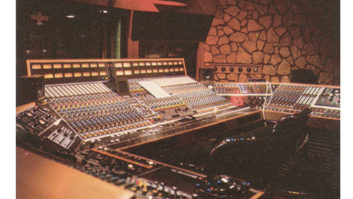
The next patch bay we’ll look at brings together the inputs and outputsof a sizable, 24-track home studio. The studio is owned by JeffCampitelli, studio drummer and rhythm guitarist for axemanextraordinaire Joe Satriani. As is common in larger studios,Campitelli’s setup employs a custom TT patch bay. (TT is theabbreviation for Tiny Telephone, the professional-standard 1/8″ jacksthat allow large patch bay systems to fit into compact spaces.)
Campitelli’s studio houses a Mackie 24•8, three Alesis ADATs, andnumerous outboard mic preamps, signal processors, synths, and soundmodules. To accommodate routing all these signals, the bays shown inFigures 2a and 2b are half-normaled and cover every tape input andoutput and the corresponding channel sends and returns. The bay shownin Figure 2c is also half-normaled and covers insert sends and returns,while the bay shown in Figure 2d is denormaled and is split betweeneffects sends and returns and mults. Campitelli has configured sixmults, each made up of one input and three outputs. Therefore, a signalgoing into mult patch point 1 is output through points 2, 3, and 4.This provides considerable processing flexibility, allowing Campitellito send, say, a snare track to three different effects units.
Note that Campitelli’s patch bay, though larger than Oppenheimer’s, isactually more straightforward. In part that’s because Oppenheimer useshis patch bay to get around the limitations of the CR-1604. But despitethe differences, some connections are the same. Campitelli’s bay shownin Figure 2e, for example, is denormaled to accommodate effects inputsand outputs–as is the case with Oppenheimer’s effects setup.Campitelli’s outboard mic preamps and compressors (see Fig. 3a) areconfigured the same way too, with ins and outs denormaled top tobottom.
In Figure 3a, we also see Campitelli’s simple yet versatile main-mixinput/output section. Balanced outputs are normaled into the DAT deckand unbalanced outputs into a cassette deck. DAT and cassette deckoutputs are normaled back into the board through the 2-track andExternal inputs. A final mix is automatically routed to DAT andcassette simultaneously.
The right side of the bay shown in Figure 3b connects seven synthsand/or sound modules into the board’s line inputs. Because the signalflow is half-normaled, it’s no problem accommodating a guest musician’ssynth–you simply plug into the bottom jacks. This breaks thehalf-normal and directs the new line-level signal to the board.Finally, the left side provides access to inserts for the mains andeach of the eight buses (submasters). By patching all inputs andoutputs into a central hub (not shown is a section covering theMackie’s 24 direct outs), Campitelli has configured a flexible patchbay that allows for easy rerouting of any signal.
DOWN THE PATCH
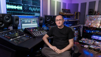
For a different take on patch bay configuration, let’s look at asection of the custom TT patch bay at Studio 684 in San Francisco, acommercial studio owned by EM contributor Buddy Saleman. Studio 684 isa 16-track facility centered around a Trident Model 65 16 x 8 x 2console, a TASCAM MS16 1-inch analog deck, and two ADATs. Sixteenrouting switches let the engineer choose between 16 analog or 16digital tracks, or a combination of the two formats.
The first thing you’ll notice about Studio 684’s patch bay (see Fig. 4)is a different layout: functions are grouped side by side as well astop to bottom. But a more important difference is that all the patchpoints are denormaled. The advantage of denormaling is that guestengineers are not constrained by what you consider normal. In otherwords, they can set up connections to their needs, desires, and quirks.And if they like to tote along a favorite mic preamp or pair ofmonitors, these can be easily incorporated into the system. That’s whydenormaled patch bays are more often found in large, commercialfacilities–because on any given day of the week a different engineermay be at the helm.
The downside, of course, is that to mix or record in a studio with alldenormaled patch points, it is first necessary to patch together allthe gear you’ll be using. For example, to print a final mix to DAT onStudio 684’s patch bay, you first have to patch the L/R stereo outputsto the L/R DAT sends. To record a DAT mix onto a cassette tape, youhave to connect the DAT returns to the cassette sends. It takes a bitmore time and thought to use a denormaled patch bay; however, theslight inconvenience is offset by increased flexibility.
To get a feel for using Studio 684’s patch bay, let’s go through thesteps of processing a vocal during mixdown. First, patch tape return 16to line in 16 so that the vocal is returned on mixer input channel 16.(You could also choose to patch the vocal on tape track 16 to any ofthe input channels on the mixer, and effectively reconfigure all thetape tracks to a desired mix sequence on the console channel strips.)Next, turn up the gain on channel 16’s aux send 1 and patch a cablefrom aux send 1 to FX 1, input 1. (Note that FX 1 is quad unit withfour discrete processing channels.) Now patch cables from FX 1 outputs1 and 2 to the returns for subgroups 7 and 8. This puts the effect onsubgroup fader controls 7 and 8–an excellent routing option in thiscase because the Trident Model 65 has 3-band EQ on its subgroups. (Inother words, you can EQ the effect!)
If you want to compress the vocal a bit, simply patch from insert send16 to compressor input 1 and from compressor output 1 to insert return16. You could also create multiple effects by chaining the signalthrough two or more processors, or, for more control, by routing eacheffect to an individual subgroup. The possibilities are virtuallyendless, which is one of the reasons to use a patch bay in the firstplace.
PATCH 22
As we’ve seen, some commercial studios favor denormaled patch bays sovisiting engineers can readily customize connections. But forconfiguring a home-studio patch bay, a more sensible approach is todetermine the studio’s “normal” setup. Finding this optimal arrangementmay require a fair amount of trial and error, but once you’veestablished what’s normal, a patch bay that’s mostly normaled (orhalf-normaled) let’s you “permanentize” that setup. Thereafter, you caneasily deviate from the norm by inserting patch cables.
Like studios in general, most patch bays are works in progress.Therefore, keep in mind that the patch bays shown here are almostcertainly not finalized, nor are they intended as recommended setups ormodels of patch bay perfection. But, by examining them closely, you cansee how other engineers have configured working patch bays for theirstudios and therefore develop some tangible plans for your routingneeds. Hopefully, each drawing will be worth a thousand words.
While writing this piece, Assistant Editor Brian Knave dreamed he wastrying to patch input and output cables to his ex-fiancée.
WHAT IS NORMAL?
Confused about normaled and half-normaled patch connections? Don’tsweat it; here’s a mini tutorial. A normaled patch connection passesany signal appearing at one front jack directly to another one. Forexample, if your DAT recorder was normaled to your console’s stereobus, the stereo mix would automatically be routed to the mixdown deck.No patch connections need to be made. However, if you do patch into anormaled jack, you break the normal connection and the signal will nowbe sent wherever you decide to route it.
A half-normaled connection allows you to break the normal and stillhave the signal go to the normaled connection and whatever destinationyou choose to route the signal to. In other words, you can split onesignal and send it to two different places. (This application iscommonly called multing.) A denormaled patch configuration means thatno connection is made until you connect two patch points by plugging acord into the appropriate jacks.