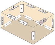
Sample placement of absorbers: In a small room, corner traps (marked as “1”) should be sufficient; in a larger space, add floor/ceiling placements (“2”).
This past winter, I taught two classes a week: Analog Recording Techniques and Studio Maintenance. The latter class started with soldering techniques, basic DC circuits — series and parallel resistance, Ohm’s Law and the Power formula — and an overview of test equipment. From these two extremes comes this month’s material, including a rant about patchbay wiring conventions and optimizing small spaces with off-the-shelf acoustic panels.
THEN AND NOW
When I started recording, the popular near-field monitors were Auratones. Even then, the geek in me brought unconventional tweaks into the mix, like having a passive subwoofer augment my customized mini-monitors or using an LA-2A as a mic preamp. What I love about teaching is integrating the stuff that worked for me then with stuff I know now.
Back then, recording a kick drum to 30 ips multitrack was a bit of a crap shoot, so while getting drum sounds, I’d always listen in Repro to see how hard the tape could be pushed before saturation turned punch into mush. Now, the Studer A827/Quantegy 499 combination is closer to what “input” sounded like. That machine’s dual metering (VU and LEDs) and the tape’s extra dynamic range yield less worry and more predictable results, especially when recording drums in the control room — a process that precludes any possibility of nuance monitoring.
I’ve always preferred drums in an open space where they can breathe rather than confining them to a booth, a corner or near a wall where low-end reflections can muck things up. Most drum booths should have a good deal of hidden space filled with bass traps, but when that is not the case, an easy fix is detailed below.
New York City’s Skyline Studios was one of my favorite spaces in which to record drums. The studio had such a great-sounding lounge just outside of the studio that I placed the drums at the sound lock — all doors open — to capture the natural ambience. Studios are smaller these days, so the modified approach has been to locate the drum kit just in front of the iso booth. This seems to have many benefits.
A kick drum has a figure-8 radiation pattern in free space, but when placed in front of the booth, the radiation is now more cardioid. One or two mics in the booth delivers a dry, well-balanced kit mix with plenty of low-end kick support.
QUICK ACOUSTI-FIX
If your booth is acoustically treated but not as you’d like it to be, the problem may be that the RT60 — the “decay” time — is uneven across the frequency spectrum. The average booth is similar in size to a full bathroom, and you know how that sounds untreated. There are some things we like about the natural reverb of a tiled room, but think about that one low-mid frequency — in the 200Hz to 250Hz range — that the male voice typically triggers.
The most common mistake is to over-treat the walls for reflections but ignore the requirements for effectively treating below 500 Hz. When there is a buildup in the low-mid to low-frequency region, the required higher-density trapping takes up quite a bit more space than just placing absorbers on the walls. One of our classrooms is a control room with an iso booth that needed such treatment but no studio, making it the perfect experiment.
Unlike upper midrange and treble, which reflect like light, low-mids and bass tend to build up at a room’s boundaries — especially corners, and not just the obvious places, but where floors meet walls and walls meet ceilings. My experience a year ago with RealTraps’ MiniTraps acoustical panels taught me enough to know what was easily possible without major modifications.

An example of good pin-1 implementation: Small touches, like Mackie’s use of all-metal ¼-inch jacks and steel rear panel on this 1642-VLZ PRO mixer, help guard against noise—creating an electrical “Firewall.”
As the school already had some “floating” absorber panels, I had students place them as mentioned. The booth is approximately a 12×8-foot space with an 8-foot ceiling. Even after two panels, everyone noticed the difference, but we kept going, figuring the drums would produce much more energy than the human voice and require the additional absorption. Drum samples are available online as a mix and as isolated mics. (Visit www.tangible-technology.com for audio samples by clicking on the IPR link.)
WIRING SEMANTICS
Questions about patchbay wiring via phone and e-mail set me off this month — big time. Two issues were raised: the semantics of “out over in” vs. “in over out” and then grounding — yeesh! Like the expression “too many cooks,” experimenting with grounding can really mess up the sauce.
For years, I thought the way I had wired patchbays — the gravity method — was the way it was done: Console sources (outputs) are on the top row and destinations (inputs) on the bottom row. The exception here is outboard gear. When I first encountered an outboard gear bay wired out-over-in, I simply made the assumption that someone decided to maintain continuity with the rest of the bay, never bothering to contemplate source and destination.
If you start at the very beginning, microphones are the first sound source. Not all bays have mic lines, but if they are in the bay, they would be located at the very top row with preamp inputs directly below. Equally logical, the next patchbay group is preamp out (insert #1 send) followed by the insert return. After that, things are literally upside down. I believe that outboard gear should be wired in-over-out because in terms of signal flow, it’s logical and gravitational. Imagine a horizontal slice across the insert send and return bay, in between which the outboard gear bay is inserted. Does it make sense now? I had to ask my Record Plant mentor, Paul Prestopino, to confirm this for me for fear I was losing my mind.
While on the subject of patchbays, there have been many schemes to resolve ground current issues — such as flying shields at one end — but the “problem” has never been with the wiring; it’s the gear that’s at fault. Eighties-era gear often used plastic-insulated jacks mounted directly to a PCB, making the shield connection the Trojan Horse of audio. In this example, the shield dumps noise on the PCB ground, to which many high-gain amplifiers are referenced. Other noises get in the way, too, such as radio and television interference (RFI and TVI, respectively). No matter what type of connectors are used, this is known as the “pin-1” issue.
The most familiar example of good pin-1 implementation is Mackie’s use of all-metal ¼-inch jacks directly secured to a metal chassis, creating an electrical “Firewall” to noise. Minimizing noise susceptibility is almost that simple and it certainly starts here. My point is not to accommodate bad gear, but to identify, fix, modify, wrap transformers around or chuck out uncooperative equipment.
Remember that unbalanced audio signals are supposed to be the domain of consumer electronics — simple systems in which very few components are close together with perhaps three feet of cable between them, max! What goes on behind an audio rack is no place for unbalanced cabling. With just a shield for noise protection and one wire for signal, the gear and its destination have no way to defend themselves against being too close to a wall-wart, inside of which is a hum-radiating transformer.
While a Firewall stops noise from sneaking into the box, it alone doesn’t stop noise induced into the signal cables, but the addition of a balanced signal path does (a twisted pair of wires for signal and a noise shield). There are three types of balanced signal configurations: transformer balanced (passive), signal balanced (active) and impedance balanced.
Two identical signals traveling down a shielded twisted-pair cable, one a mirror image of the other (180 degrees out-of-phase), is easy to visualize. If brought up on a mixer as two independent channels, then the signals would cancel. If subtracted by a differential amplifier (what balanced inputs are), then the signals add up while canceling the noise common to both wires. The relationship of amplifying the audio while rejecting noise is known as the common mode rejection ratio (CMRR).
Impedance balanced is a little tougher to grasp because both signal wires have the same source impedance (stay with me now), but only one of the wires carries a modulated signal. For example, let’s say the signal-modulated wire is being driven by an output amplifier with a 47-ohm impedance. (It’s a “source,” get it?) By tying the unmodulated wire to ground through a 47-ohm resistor, hum will be equally induced into both “signal” wires so that the destination — a balanced input/differential amplifier — can do its job of canceling the noise common to both wires.
I’ve always wired unbalanced gear with balanced cabling and this does reduce induced noise by an obvious amount, albeit not as much with a true impedance balanced circuit. If you knew the output impedance of an unbalanced device, then the trick in the paragraph above could improve things considerably; alternatively, using a transformer at the destination would be the easier fix.
Eddie is thankful that his technical background has kept his bag of tricks full and a bit ahead of the curve, but he sometimes regrets not getting psych and MBA degrees.
