Live recording — in studio or onstage — is an adrenaline rush like no other. Compared to tracking one instrument/source at a time, interacting musicians add much more to the mix than the sum of the tracks. Live recording is the ultimate multitasking experience and allows no retakes.
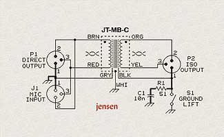
Figure 1: Single channel mic splitter schematic, courtesy Jensen Transformers. Note separate shields for each transformer winding, and the ground and lift paths in bold.
Training Ground
Even in a “controlled” environment, problems can arise. Sharing mics is an everyday occurrence at live gigs, where front-of-house and onstage monitor consoles require independent control of the mix. When simultaneous recording is part of the equation, the extra gear is like an invasive species, stressing each piece of gear in the chain, from the microphone, through each connector and cable to preamp and converter.
The distance between the source (mics) and multiple destinations (preamps) in multiple locations (FOH, monitor mixer and remote recording rig) from various power sources will “find” problematic gear. In addition to power-related hum and buzz, proximity to broadcast transmitters increases the possibility of radio frequency and television interference (RFI/TVI). Once an urban issue, “wireless” problems now seem to crop up everywhere.
Off the Shelf
As in every other aspect of our biz, technology booms and budget cuts in remote recording inspire a D.I.Y. approach. The beginning of this yellow-brick road is a mic splitter. Recording engineer Tom Garneau uses four 8-channel Whirlwind splitters. There are four versions of this splitter box; the one Garmeau uses is the most spendy because it has the most useful features. The Whirlwind SB08P11G (about $560) has two sets of eight outputs — one set has a hard-wired mic loop-thru; the other set is transformer-isolated and includes a ground lift switch. A schematic of a basic, single-channel mic splitter is shown in Figure 1.
Who Said, “Easy as One Two Three?”
Properly implemented, balanced gear in a fully balanced system should work out of the box with standard cables and minimal fuss. But as anyone with enough audio gear knows, as soon as the system requires multiple power outlets in multiple rooms, something in the system is likely to have a power-related hum and/or buzz. There are also an assortment of other potential noises, from computers — video monitor and hard drive hash — and cell phone chirps, all of it a sign that “someone” is not with the program.
Over the years, a variety of tricks have been conjured up to sooth the weak links. There are wiring Band-Aids like “flying shields,” use of ground adapters as “ground lifters,” wooden rack rails, etc. The true fixes are few. For example, much time, effort and money has been invested in external ground distribution systems, but it’s all for naught if the gear itself is flawed. Within the gear, internal ground distribution is critical, and as engineers are inclined to use all varieties of vintage gear, it’s important that all of it be diligently inspected and made compliant. And recognizing flawed gear isn’t always so obvious because compliant gear will often look like the problem child rather than the peacemaker.
Step 1, Pin 1
The so-called “ground loop” is often blamed for unwanted noises. The actual cause is noise currents flowing in the cable shield between two pieces of equipment, at least one of which is internally flawed. In the realm of “normal,” the shield takes a lot of abuse, all of the time. No two electronic devices will ever be at the exact same ground potential, especially when not in the same rack or power strip. The shield also absorbs radiated noise (induction from power transformers) and acts like an antenna for RFI/TVI.
True differential (balanced) inputs reject induced noises by way of the Common-Mode Rejection Ratio (CMRR), but the other “noises” can creep into gear electronics via poorly implemented “pin 1 issue.” Though not exclusive to the XLR connector, noise current in the shield can and should be safely escorted away from the audio signal path. To accomplish this, cable shields must be connected at the point of entry — aka, the chassis — or what I like to call the “noise Firewall.” This is not always the case, leading to the many Band-Aids that have been conjured up over the years.
To ensure that a good circuit design is not compromised, manufacturers in the know use connectors that make an automatic pin-1 to chassis connection. This is done using the shortest, lowest-impedance connection possible that must also be mechanically reliable to ensure long-term performance. It’s admittedly simpler to execute than understand, but with the help offered on Rane’s Website, I’ve borrowed a few examples.

Figure 2: Inside a mic, the black pin-1 to chassis wire is close to zero ohms at audio frequencies, but not at radio frequencies. The solution is to tie pin-1 to the XLR’s chassis lug and relocate the audio circuit’s orange ground wire.
When Is a Wire No Longer a Wire?
A piece of wire is an illusion of sorts because its behavior is environmentally dependent. We can all agree that a short piece of wire, even a thin one, should have pretty close to zero-ohms resistance at DC (when using a multimeter). At audio frequencies (AC), the quantity formerly known as resistance becomes impedance — still measured in ohms, but not with a standard multimeter. The name change implies that we may be in for surprises.
Figure 3: Pin-1 ties to the XLR connector’s chassis lug through a thin wire. Here, the screw locking the XLR to the mic body must be clean and secure.
Above 100 kHz, the true meaning of impedance begins to reveal itself, as the resistance of wire now changes with frequency from zero ohms at DC to several ohms at radio frequencies. What was thought of as a simple piece of ground wire can become a Trojan Noise Horse, infiltrating the electronic Firewall and delivering both power-related hum and buzz, as well as transmitted noise into the high-gain inner sanctum of condenser mics and mic preamps.
Out-of-Body Experience
Just when you thought it was safe to blame the receiving end of your recording gear, the source and its connectors can also be suspected. Inside the microphone in Fig. 2, the length of innocent black wire from pin 1 to chassis allows it to have an inductive reactance of 4 ohms at a frequency of 56 MHz (TV channel 2). The noise is both inserted into the signal ground and radiated into vulnerable, high-impedance circuitry.
Another microphone in Fig. 3, with a thin 1cm wire between the XLR’s chassis lug and pin-1, yields 2 ohms of inductive reactance at 60 MHz, inserting RF noise into the signal ground. The green arrow indicates how the signal ground might be relocated to the lug to take the wire out of the equation. (Note: The author-annotated illustrations in Figs. 2 and 3 are based on images courtesy of Jim Brown, Audio Systems Group, Rane and ©2003 Syn-Aud-Con.)
These days, digital snakes and mixers, high-speed networking and fiber-optic interconnects solve (or hide) some of the common problems that plagued analog audio for years. But analog has a lot to teach us if only we listen. Digital audio can be affected by similar problems but can manage to function until the data errors can no longer be concealed, a condition sometimes referred to as “falling off the digital cliff.” But that’s a topic for another day.
Eddie’s live remote experience includes Live Aid, Farm Aid, Joe Jackson and Luciano Pavarotti on the following remote trucks: Record Plant, Remote Recording Services and Le Mobile. Eddie thanks Jim Brown, Rane, Syn-Aud-Con and Jensen for their informational generosity.