Several years ago, the introduction of digital television, along
with the auction of bandwidth to digital cellular services, heralded
major changes in the American RF environment. Responsibility for more
than a few channels of wireless in a U.S. metropolitan area is now a
recipe for trouble, and the radio congestion continues to get
worse.
The airwaves of New York and Los Angeles are determining factors in
which wireless products will go on tour today, and as more digital TV
stations come online during the next five years, the situation will
become increasingly complex. Manufacturers such as Shure and Sennheiser
have made a concerted effort to educate users about frequency
coordination and potential problems, but the typical audio user of
wireless mics can no longer simply turn them on and hope for the
best.
The great majority of professional audio engineers remain incidental
users of wireless technology, but there are a handful of wireless
specialists to help guide our industry through the miasma of FCC
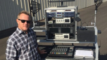
regulations and potential hot spots. Mix caught up with ex-Navy
ECM technician and RF guru James Stoffo in Florida. Stoffo takes RF
very seriously, and he is known for leaving his cell phone turned off.
He emphasizes that a few simple procedures can vastly improve your odds
of wireless success.
He begins by reminding me that the main problem with RF is that our
senses are not naturally tuned to it, as the radio band, between 10 kHz
and 300 GHz) falls above sound waves and below light. “Often,
your first indication of an RF problem is when your wireless mic
clamors through the P.A. in a loud burst or goes mysteriously
silent,” Stoffo says. “We never had big creatures that
chased us and emitted RF before they pounced on us. You can’t see it,
can’t hear it; you just have to know that it’s there and understand how
to manipulate it.”
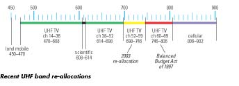
Pro audio is really only concerned with a small slice of the radio
band, and it’s getting smaller every day. The UHF band, where nearly
all professional wireless mics operate these days, starts at 470 MHz
and goes up to 806 MHz (TV channels 14 through 69, with 37 saved for
radio astronomy). Less than a decade ago, there were fewer than a dozen
UHF stations in most areas, leaving more than 75 percent of the UHF
band wide open.
Things started changing five years ago. The introduction of digital
television meant the adoption of parallel transmissions, where the
analog TV broadcasts continue and a second digital transmission is
brought in on a new frequency. Every analog TV station will eventually
be duplicated by its digital broadcast on a second frequency, though
the FCC imagines that sometime later in this decade, we’ll all have
purchased DTV sets and the analog transmissions can then cease. In the
meantime, there are more UHF TV broadcasts every month.
As of this writing, half of the TV stations have begun digital
transmissions. The other 800 of the 1,600 total TV stations in the U.S.
can be expected to begin digital transmission on new frequencies during
the next couple of years. Future problems may arise, as the FCC’s
reallocation of the upper UHF band will force TV broadcasts in America
below 700 MHz.
RF WAR GAMES
One of Stoffo’s many high-profile gigs is RF coordinator at the
Super Bowl, where last year there were more than 1,000 frequencies in
use. And it wasn’t just audio, but all sorts of wireless intercom,
emergency, security, video and broadcast services. Long before kickoff,
a day is set aside for what Stoffo calls “war games,” where
users turn on all of the wireless equipment used by all of the
departments to find out how it interacts.
“You don’t need a fancy RF analyzer or even a scanner to find
intermods,” Stoffo points out. “It’s very easy: Turn all
the transmitters on and then turn each transmitter off one at a
time.” If the other transmitters are causing intermods on that
one frequency, then they’ll show up as an RF signal at the turned-off
transmitter’s receiver. This is the essence of RF war games — a
real-world reality check to see which systems are interfering with
others.
When there’s enough interference on an RF system, and when that
transmitter’s signal fades or drops out, that interference can be hot
enough to pass a burst of noise into the receiver and the sound system
to which it’s connected. This can happen in several ways: when someone
touches the antenna, when the battery dies or when the transmitter
enters a dropout location. And it doesn’t have to be on a receiver’s
frequency, just nearby. Any RF that falls within a receiver’s passband
that’s hot enough can open squelch and pass noise. The noise is
typically 20 dB hotter than the signal it replaces, so it’s usually a
“showstopper.”

Even when these intermod products don’t fall right on top of a
receiver’s frequency, they reduce the signal-to-noise ratio of a
wireless system on a nearby frequency because that signal desensitizes
the receiver’s front end, reducing the sound quality of the wireless
transmission.
Stoffo also points out that the likelihood of intermods is increased
when two transmitters are in close proximity. “When two actors
with body mics hug or kiss, the signal from RF number 1 gets into RF
number 2, mixes with its signal, and retransmits not only an intermod,
but also an intermod of an intermod, as the intermod itself gets back
into the other transmitter,” he explains. “This is the RF
equivalent of pointing your vocal mic right into the floor
monitor.”
The worst-case situation for multi-unit systems is typical of how
many engineers start up their wireless mics to check them: Turn them
all on and set them down in a row on a section of the mixing board,
which also happens to be near the receivers. When you turn on your
mics, separate each transmitter from the next by a couple of feet,
perhaps putting them on widely spaced stands, and keep them 15 to 20
feet from the rack of receivers or the antennae so that they don’t
overload the receiver’s front end.
If it isn’t already apparent, setting up a wireless system requires
you to adhere to the “an ounce of prevention is worth a pound of
cure” maxim. And as we head into the next five years, Stoffo
says, the ABCs of wireless remind us that attention to the basics is
the solution to many RF problems.
A IS FOR ANTENNA
Experienced engineers who just use the whip antennae supplied with
each receiver are careful to arrange the two antennae of a diversity
wireless system in a 90-degree V shape. Radio signals travel through
space in a particular plane that is determined by the transmitter’s
antenna. “Imagine a rap artist who holds their handheld mic
horizontal to the floor. That RF signal is traveling on a horizontal
plane,” Stoffo describes. “We say that the electrical
component of the electromagnetic wave is horizontally polarized.”
He then refers to the concept of “aperture,” explaining
that if an antenna on the receiver is parallel to the transmitter’s
antenna, then the transfer of energy from one to the other is
maximized. If your diversity system only has whip antennae, keeping
them perpendicular to each other maximizes their coverage of all
possible angles of the transmitter’s antenna.
Besides whips, there are directional antennae that have several
important benefits: They can be located remotely from the receiver,
they add gain and they favor signals coming from one direction. Unless
you need to receive signals from all directions, whip antennae will put
your wireless system at a disadvantage. Most pro audio action takes
place onstage, which means the signals are in a particular direction.
This directionality can be used to attenuate interference coming from
elsewhere. By adding gain in one direction and reducing it in others,
the use of directional antennae increases signal-to-noise to provide
improved wireless transmission and, as a result, better sound.
“The only time you’ll see me using an omni antenna is when I’m
doing a radio sweep with my RF analyzer,” Stoffo points out.
“A directional antenna typically raises signal-to-noise by over a
dozen decibels.”
One common type of directional antenna is the “log periodic
dipole array,” or “log” for short. It’s also
sometimes called a “paddle” because it resembles a pingpong
paddle. These typically have a 70-degree coverage pattern, add about 6
dB of gain and can cover hundreds of MHz of bandwidth — wide
enough for many different RF systems.
Usually, paddle antennae are vertically oriented on mic stands.
Occasionally, someone mistakenly uses a stereo mic bar to mount two
antennae on a single stand. This not only places them in the same
polarization, but also less than a wavelength apart. A better
arrangement would be one that orients the two paddles perpendicular to
each other (by putting at least one on a boom arm) and places them at
least several feet apart.
Another less-common antenna type is the Yagi, which is highly
directional, like a shotgun mic, and is tuned to a narrower bandwidth,
usually that of a single RF system, about 30MHz wide. It also has
almost twice the gain of a log. It looks like your grandma’s old
rooftop TV antenna, with a single long axis and several shorter
crosspieces. In problem areas, these can be used for high focus and
high rejection.
A third type is the helical antenna, which is a clear plastic tube
with a ribbon of copper wound around its inside like a candy cane and a
circular wire mesh at one end. It has about the same gain as a Yagi but
covers all 360 degrees of RF polarization at once. Stoffo’s company,
Professional Wireless Systems, makes helical antennae, so naturally he
uses only helical on the Super Bowl, where he can use anything he
wants.
Under the rule of reciprocity, a transmit antenna can be used for
the same frequencies as a receiver. This is why helical antennae have
proven successful as transmit antennae for in-ear monitor systems.
Their ability to modulate RF through all angles of polarization makes
them less susceptible to dropouts than the usual paddles or whips
because they permit 100 percent of possible energy transfer no matter
what the orientation of the receiver’s antenna — especially
important as IEM beltpacks are not diversity systems.
B IS FOR BUNNY
“The last dozen problems I’ve had with RF all had to do with
batteries,” Stoffo says, “so I’ve done a lot of testing on
the different makes and models. We’ve used [Duracell] ProCells, and
sometimes they’ve lasted longer, but often they don’t. The Energizer is
the most consistent. That way, we know how many hours of use to
expect.”
Lithium batteries typically last twice as long as a Ni-Cad, but are
only found at professional battery outlets. Most of us are going to get
AA, 9-volt or Ni-Cads from an industrial battery supplier, not a local
supermarket. Stoffo does warn that though rechargeable batteries are
tempting for economic reasons, at best they’re only good for half as
long, which may not be enough for many shows. Also, if the batteries
are regularly recharged before they’re dead, memory effect kicks in and
you’ll no longer get full use.
Stoffo recommends to always meter batteries before putting them into
play and using a proper battery meter, instead of an ohm meter as it
puts a load on the battery to get a correct reading. The most
cost-effective tool for your wireless system is a dedicated battery
tester. You only have to suffer the embarrassment of putting a
half-dead battery into play once before this small investment makes
sense. Stoffo also points out that once you start using a battery, it
begins the process of losing its charge so that it’s no longer
dependable for future use. Also, many newer transmitters use a DC
regulator to get the most out of the battery, which means that when
they die, they die fast. Also, the onboard fuel gauges are not
necessarily accurate.
C IS FOR COORDINATION
Frequency coordination is more than simply fitting wireless systems
in and around the list of known broadcasters in an area. The term
intermodulation describes the interaction of any two nearby frequencies
to create a third frequency. Stoffo uses a color metaphor to explain:
“Red and yellow combine to make orange. If you have two wireless
mics and they’re on the red and yellow frequencies, you don’t want to
try to use a third on the orange frequencies because you’re already
generating signals there as a byproduct of the first two.” As the
number of wireless frequencies increases, the number of intermod
products increases exponentially. A typical rack of eight RF units
produces an additional 27 third-order intermods. This is why
manufacturers have preset groups of frequencies that are carefully
designed to work when multiple systems are used together. Most of that
information is available at the manufacturer’s Website.
Mark Frink is Mix‘s sound reinforcement editor.