Back in March, Mix asked three writers to outfit project studios in the $10k, $25k and $50k price ranges. In his opening paragraph, Robert Hanson started off by saying, “Obviously, [$10k is] not enough for lavish acoustic treatment.” Of $50k, Paul Verna allotted $1,000 for materials, hardly “lavish.”
Few project studio owners start at the very beginning with room design. Project studio budgets are all over the map, but there is a good chance that acoustics take a back seat to gear. Don’t worry; I am not going to scold you. As an engineer and technician, I’ve seen it all, from the funkiest Civil War-era factory installation (in Brooklyn) to those glam, chi-chi places where all the big records and broadcasts are done. Everybody skimps somewhere.
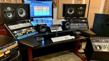
One glaring error in most “thrown together” control rooms is the lack of symmetry. Monitor placement should be symmetrical within the room, and the space from the monitors to your ears should be as equitable from left to right as possible. Often, equipment gets “temporarily” piled up on top of racks, only to live there indefinitely, sometimes nearly blocking one monitor. If this sounds (or looks) familiar, then it’s time to plan a cleanup. Plus, work flows more efficiently and with less fatigue when the room works with you and not against you. This becomes more important if your personal project studio starts taking on outside business and engineers. For a refresher course on monitor placement, absorption and room modeling, check out the three sidebars to this article.
DRAWN FROM LIFE
The first step is to draw the space in question with as much detail as possible, including floor-to-ceiling dimensions. This simple exercise alone will provide a visual perspective that you may have missed. If you are geek-inclined, there are various online programs that will calculate reverb time at critical frequency bands, allowing construction materials and wall coverings to be factored in to see the difference they can make.
The ads in this magazine combined with a good search engine (like www.google.com) are resources for locating people and literature. Nothing replaces a “house call,” but now it is possible to find someone who communicates at your level and price range via e-mail. Your room image, once in e-form, plus experience with the space in question can provide valuable feedback to the online sonic doctor.
One acoustic design site emphasized the importance of honesty, for which I could find no formula. But, seriously, when advice is given that doesn’t jive with your gut, get a second or even a third opinion.
CLAP YOUR HANDS
Building a room from scratch allows every detail to be addressed, from shape to isolation, power to air conditioning. A symmetrical space without parallel surfaces is the optimum shape, something in the ballpark of a pentagon or a modified diamond. More often than not, however, we are dealt a difficult hand — such as the small office space with four parallel walls, which can be sonically challenging. You know what such a room can sound like empty — clap your hands and “boing,” it’s like the inside of a basketball. Fortunately, when a room is filled up with gear, the acoustics can settle down somewhat. But it’s not always that easy. Controlling reflections is one of the primary acoustical tweaks that can make a space work. The smaller the space, the greater the challenge.
Many control room pictures have graced the cover of Mix, and, over the years, architectural drawings of control rooms have occasionally appeared between the covers. Some may have inspired an idea or two for your own facility. Looks can be deceiving, though, as these 2-D images do not reveal all of the secrets on or behind the walls.
A rigid, flat surface is sonically reflective across the spectrum; bare walls in the front of the control room should be avoided, because high frequencies can bounce around. You want only direct sound from the monitors to reach the engineer’s position. Sculpted foam, carpet, curtains or covered Fiberglass will tame the early reflections that can mess up the stereo image. Behind the engineer’s position, diffusion via irregular surfaces like bookshelves, rough stone or an “engineered” diffuser can do the trick. An acoustician can diagnose some aspects of a room fairly quickly and tell you where to put this stuff.
A few months ago, I attended an Audio-Technica microphone demo at Flyte Time Studios (www.flytetyme.com), home to producers Jimmy Jam and Terry Lewis. My good friend Ted (who was coincidentally building a studio below his two-car garage) came along. All along, I had been nudging Ted to excavate as deep as possible to gain some extra ceiling height. During the studio tour, Ted noticed the low ceiling in the control room. Chief engineer Brad Yost pointed out that there was an additional 20 feet above the acoustically transparent ceiling, a luxury for sure, but one that encourages us to “think outside the box.”
HOW LONG HAS THIS BEEN GOING ON?
The speed of sound is 1,130 feet per second at room temperature (72°F), so the formula reads: wavelength = 1,130/frequency. A guitar’s low “E” string is 165 Hz, and, when reproduced through a loudspeaker, it generates a wave 6.8 feet long! So, it only stands to reason that the low “E” on a bass guitar will generate 41.25 Hz and 82.5 Hz (fundamental and harmonics) with wavelengths of 27.3 feet and 13.65 feet, respectively. I hope it is becoming clearer how room size and the reflections therein become obstacles to the accurate reproduction of low frequencies.
Luca, my 2-year-old, might describe mid- to high frequencies as “really cute and tiny.” Although he has no idea what sound looks like, it is an important concept to grasp for those of us who play with audio. All frequencies take up physical space, and several Websites offer online calculators to help us visualize them, including www.eatel.net/~amptech/elecdisc/disc/frequency.htm and www.mcsquared.com. And by the way, here are some cute and tiny wavelengths: 2,500 Hz is 0.452 feet (5.4 inches); 5 kHz is 0.226 feet (2.7 inches); 10 kHz is 0.113 feet (1.3 inches), and 20 kHz is 0.0565 feet or 0.678 inches. (See also www.contrabass.com/pages/frequency.html, and Research in Guitar Acoustics at www.phys.unsw.edu.au/music/guitar/.)
As you can see, low-frequency wavelengths are rather large. From the sound source to one reflective surface — in just one dimension — a single bass note can create a wave of additive peaks and de-constructive dips, making notes hard to judge in a small, untreated room. Put up a 50Hz bass tone, walk around the room, and hear the peaks and valleys for yourself. I always use an analog VU meter to judge bass note levels in a mix, using those old standby optical limiters — the LA-2A, LA-3A and even the LA-4 — to smooth note-to-note inconsistencies.
To absorb bass requires more mass — the equivalent of a boxer’s punching bag, only with more surface area. The most simple panel designs can be thought of as floating walls; they take the punch so that the wall behind doesn’t have to, minimizing the amount of energy to hit the wall and obstructing any reflection back into the primary listening area. A broadband absorber is a simple solution that can be effective from high frequencies down to 125 Hz, depending on panel size and distance from the wall. Low frequencies below 125 Hz require specially designed resonators or bass traps to absorb the larger waves.
Almost any acoustic treatment will absorb high to mid-frequencies when mounted directly on the wall. As frequency drops, however, not only must panel size and density be increased, but space must be added between it and the wall. At this point, many acousticians prefer Type 703 Rigid Fiberglass insulation for its density; it is commonly available in thicknesses from 1 inch to 6 inches.
FIVE POINT WONDER
If you think a stereo room is a challenge, 5.1 can be even more so. My first 5.1 seminar (spring ’98) was decidedly underwhelming. Thinking I could easily do better and certainly do no worse, I cashed in the chips to snag a pair of Dynaudio monitors (BM-15A), a Tannoy sub and a Studio Technologies monitor selector for my extremely humble New York control room. I nudged placement and tweaked levels until things felt comfortable, opened two stereo mixes on my Soundscape workstation and remixed them in 5.1 just in time for the ’98 AES.
I then took a DTRS tape from booth to Dolby-approved studio, but it was a JBL listening room at a trade show that blew me away. For a temporary setup, a generic utility room at San Francisco’s Moscone Center had been transformed into a great-sounding space. It was outfitted with JBL’s then-new LSR monitors, which are remarkably affordable and quite effective.
When a mix translates to another system so well, the first inclination is a pat on the back followed by the question, “Where is the magic coming from?” I immediately noticed the unconventional setup. The monitors were not “square” with the room. Instead, the virtual room-within-a-room was rotated 45°, the “walls” being defined by strategically positioned baffles. The end result was plenty of good seats rather than one narrow sweet spot. The figure on page 138 is an example of monitor placement.
Through investigation, I learned that the demo room design was by David Kimm (then developer of JBL’s LSR Series, now president of Apogee) and his golden ears partner John Eargle. In addition to their clever setup, the LSR Series boasts an extremely respectable off-axis response with dispersion characteristics optimized for both horizontal and vertical planes. This helps make a loudspeaker system sound good, even when the listener is not in the sweet spot.
HOME AT LAST
Three years ago, I purchased a house, claimed a spare bedroom for the control room and quickly set up all the gear before baby made three. I chose the “Kimm” approach, not knowing it was his idea until I interviewed him for this article. The room worked, but I knew that additional treatment was needed — not to mention new rack furniture, speaker stands, etc. — to make everything fit in the new space. After two years of listening too hard, I began measuring and documenting the space. I coincidentally made friends with acoustician Terry Hazelrig via some Internet business. Terry looked at my drawing, thought it unconventional at first and then did the numbers. I think he was surprised.
There is no such thing as a perfect room, but there are better rooms. The goal isn’t spectrum-analyzer-flat — the ear isn’t flat, nor is its sensitivity the same at all levels. (Please visit http://hyperphysics.phyastr.gsu.edu/hbase/sound/eqloud.html to see the ear’s sensitivity.) Aside from minimizing destructive reflections, your personal taste should be factored in via monitor choice and placement — plus a comfortable, safe listening level — that will ultimately create a curve that suits your preference.
Eddie would like to thank Hector LaTorre, Wade MacGregor, David Kimm and Terry Hazelrig for their insights.
RT60
RT60 is the amount of time, in seconds, for reverb to decay 60 dB below the initial value. Predictions are based on using known surface materials and their absorption coefficients, calculated in 1-octave frequency bands using Sabine equations. The table shows the numbers for an untreated space. Through design and acoustic treatment, the preferred RT60 values should fall between .35 and 0.5 seconds for each band, matching as close as possible.
You can check the RT60 of your space by plugging in materials and dimensions at www.trinitysoundcompany.com/rt60.html, but if you want to party with the numbers in your own intimate setting, see the table.
— Eddie Ciletti
ABSORPTION
By Terry Hazelrig
The absorption coefficient describes how a material behaves, but
what is it actually measuring? The material being tested is placed
directly on a surface in a reverb chamber of known reverb time.
Loudspeakers excite the room with noise, and the reverberant decay is
recorded before and after the sample is placed. Visit www.studiotips.com/absorb1.html to see absorption
coefficients of common materials.
If the perfect “total” absorption is equal to 1.00, then
why are coefficients higher than 1.00 published, and what do they mean?
In addition to surface absorption, the edges of the sample material
will make it appear larger and more effective at absorbing than it will
be in the real world. There is no standard for dealing with
coefficients greater than unity, so the manufacturer either rounds off
to 0.99 or publishes the “better than perfect” numbers.
This makes it hard to shop by comparison.
MONITOR REPLACEMENT
By Terry Hazelrig
“Quality” speakers alone do not guarantee accurate
reproduction. All are subject to the laws of physics, especially those
relating to boundaries such as walls, ceilings and floors.
A speaker placed in the middle of a room effectively radiates low
frequencies equally in all directions or into “full space.”
Bass waves are mostly nondirectional and radiate everywhere, but when
placed near a wall, a speaker’s—apparent—low-frequency
response will increase by as much as 3 dB. This boost results from half
of the speaker’s low-frequency output being reflected off the wall into
“half space.” A speaker placed in a corner (quarter space)
will get up to a 6dB boost in the low-frequency region.
A loudspeaker can also transmit energy indirectly through the room’s
structural members. Because the speed of sound is faster through a
denser medium than it is through air, a monitor that’s in contact with
a surface can create comb filtering in the low-mid region: Sound
transmitted through the wall and/or floor will reach the mix position
before the direct signal through the air. To de-couple the speakers
from the structure, isolate the speakers using rubber, Fiberglass or
some other resilient material. (www.diyacoustics.com).
