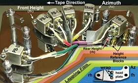
Figure: the mysteries of the Space Echo revealed
A year ago in this space, I mentioned two tape-based delay units: a Roland Space Echo and a solid-state Echoplex. Both rely on something in rare supply these days: magnetic recording tape — and not just any tape will do.
Back when professional tape was plentiful, I confess to replacing Space Echo endless loops with whatever was readily available at the time — Ampex 456 or 3M 250. My logic wasn’t exactly sound. What’s good for a pro machine will initially work in a tape-delay box, but over time there are consequences, like friction that accelerates head wear and causes drag on the capstan and pinch roller. Pro audio tape is thicker and less flexible than the thinner, more specialized version used to get that authentic “Be-Bop-a-Lula” tone: 1-mil thickness compared to 1.5 mils (1 mil = 0.001 inches).
The RE-301 Space Echo has six heads (erase, record and four staggered playback heads) so a little additional friction per head adds up — each head will wear more than the one before it. For example, 1.5-mil tape exits the bin at 0.5 ounces of tension (that’s before playback head PB-4 in the figure below) vs. 1.9 ounces of tension after PB-3. Contrast this with 0.2 ounces of tension pre-PB-4 and 0.4 ounces post-PB-3 for 1-mil lubricated tape. To a tape head, that’s a huge life extension. Compound the excess tension of 1.5-mil tape with the inappropriate use of a screwdriver, and you’ve got a head assembly with multiple wear patterns.
A Lá Cart
There are two basic types of endless loop tape systems: cartridge and bin. All but one Echoplex model used the former, as did the first-generation Space Echo. To reduce the friction of tape against tape — all layers constantly moving against each other — a graphite back-coating was added. The same magic made 8-track cartridges possible. The Echoplex Sireko and subsequent Space Echo models employed the more forgiving “bin loop” alternative that eliminated tape-to-tape friction, but all relied on a felt pad to maintain tension for consistent tape path and tape-to-head contact.
You’ll know that friction took its toll on the heads when performance becomes inconsistent (drop-outs) or exhibits diminished high-end response. The radius or curved contour of the head face becomes flattened over time, reducing the tape-to-head contact pressure.
Head contour can be restored by “politely” sanding away the non-worn areas until they’re level with the worn area, after which the radius can be restored. Called “lapping,” the process begins with fine sandpaper — like 500 or 1,000 grit — followed by successively finer grades of “lapping film” that end up more like the texture of paper than sand for polishing.
Cinque Terre
When working on any tape machine, the first step is demagnetizing all tools that will be in contact with the head assembly and surrounding areas. As the machine in question had head-height issues, I ballparked the height first, before disassembly. As you can see in the figure, three screws on each head mount allow head movement in every plane — front and rear height adjustments affect “zenith” (front-to-back tilt), azimuth sets the side-to-side tilt. All playback head gaps must match the azimuth of the record head. And the erase, record and playback heads are application-specific and are not interchangeable.
In an ideal world, a set of mechanical reference blocks and a test tape would be used to set the mechanical parameters. In lieu of such tools, note the pair of brass stand-offs that fit under the head-mounting plate (in the figure, to the right, under PB-4). The distance from deck top to plate bottom is a wee bit more than 0.185 inches. With the stand-offs as reference, getting the lapped heads back into position should require only minor tweaking.
Wires exit the rear of Echoplex heads and must be unsoldered at their destination. Space Echo heads have terminals to which wires are tack-soldered. After the heads are disconnected, their mounting plates can be removed from the deck (lower-right corner of the figure) and the head unscrewed from the plate. These two screws also affect head wrap — centering the head’s gap at the point of contact to optimize high-frequency output. I used a Sharpie® to outline the head position before removing it from the plate. If the heads are not centered, observing the wear pattern can guide in the process of ballparking the new head position.
After the heads were made smooth, the steps were all reversed, with the figure serving as the wiring reference. To confirm the coarse mechanical alignment, the head face is “painted” with a Sharpie ink that will be worn away by tape travel, revealing whether the zenith is correct and how well the head gaps and height are centered.
Once the mechanics were ballparked, an azimuth test tape was made on a calibrated 2-track deck, recording pink noise at 7.5 ips. The tape was then spliced into a loop. (Note that the erase and record heads were left disconnected so the playback heads could be adjusted. The Space Echo’s Mode switch allows monitoring each playback head separately.) Assuming all other mechanicals are correct, getting the azimuth right is as easy as adjusting for the brightest pink noise. There’s only one right way and it will be obvious. After the playback heads were tweaked, the record and erase heads were connected, and pink noise was injected so the record azimuth could be adjusted.
Optimizing a tape machine poses a fun set of challenges that minimize the negative aspects of working with analog tape so you can enjoy the positives. It’s not just the sound of tape and saturation or speed variations that create a subtle chorus effect, but the ability to infuse emotion into an effect in real time. For some reason, digital versions of analog effects rarely have knobs. And while the precision of increment/decrement and the ability to recall and automate are awesome, the power of a simple, real-time human interface is an important part of the emotional equation.
For more Eddie Ciletti, visit
www.tangible-technology.com.
AUDIO SCIENCE
CALCULATING DELAY TIME
Tape-delay devices can add some creativity to your productions. It’s also easy to make single-delay effects using any pro analog recorder — a great way to put an old 2-track to use. But what’s the delay time? If there’s a 2-inch spacing between the record and play heads and the tape speed is 7.5 ips, then the delay is equal to 2 divided by 7.5 inches/sec = 0.260 sec or 260 milliseconds. At 15 ips, that amount would be halved for 130 ms. For more variations, use the varispeed control to increase/decrease the delay time. And for more outré regeneration effects, try mixing a small amount of the delayed signal back into the record input.
— Eddie Ciletti