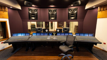
Front view of Massey’s mix room with Harrison Trion console and QRD diffusers along sidewall. The monitors (JBL 4648A LF boxes with BMS HF drivers on Community horns) and a Meyer 650 subwoofer are located behind perforated screen.
It was a dream come true for a guy like me: Not only would I design the acoustics for a major player’s personal mix room, but I’d be working in a dream location—a wooded hillside in Ojai, Calif.
My first visit to Paul Massey’s future film mixing room revealed only a 40×22-foot concrete slab and a partial course or two of Perform Wall blocks that would comprise the walls of the studio-to-be. (For information on Perform Wall, see the sidebar “Perform Wall—What the Heck is That?”) My goals were simple: I wanted a neutral room so the mixes that Massey heard would match what he was recording. And because he normally mixes in the Cary Grant Theatre at Sony Pictures Entertainment (Culver City, Calif.), it was imperative that mixes from his new studio translate to that room.
STEP ONE: THE SHELL GAME
Usually, I’m presented with the dimensions of a shell in an existing building. On this project, I could optimize the room size. The best acoustic performance starts with proper room dimensions—get them right, and the room modes will be well-distributed in the frequency domain, thus avoiding a lot of problems.
The room’s width was set—literally—in concrete, but I could adjust the height and length by adjusting the ceiling elevation and the rear-wall position. Using a spreadsheet designed to calculate room modes, I plugged in initial dimensions and calculated the modes. Like all first iterations, the modes weren’t distributed very well. I adjusted the ceiling elevation and the rear wall position by a few inches until the modes were evenly distributed. With a decent idea of what the room would do in the LF region, Massey and the architect were notified of the changes and the contractor finished the shell to these specs.
It is commonly thought that non-parallel walls and a canted ceiling are the way to go in a sonically sensitive room, but I disagree. Flat, plumb and square can be good. In a rectangular room, you have a better idea of what performance to expect. You can predict the room modes and their location, and they won’t be distorted by varying dimensions. This makes controlling bass response easier, and as listeners move around the room, they’ll get a more consistent sonic performance.
In a mix room, this consistency is important so that the mixer and client hear essentially the same thing. But nothing comes for free, so the price you pay for predictable and consistent is flutter echo. Unpredictable and inconsistent isn’t fixable—no absorption or diffusion or whatever will fix it—so you own it for the life of the room. You might mask it with a bandage, but the problem is always there.
Reflections and canted surfaces can be calculated and drawn, yet to my thinking the errors and surprises of actual construction make a room with non-parallel surfaces a bit more of a roll of the dice. I’m not a gambler; I like to know what’s going on. And after all the calculations, you still have distorted room modes. To me, it’s not worth it. Secondly, rectangular rooms are easier and cheaper to build. That will make your client happier, especially if you’re the client. Flutter echoes, however, are fixable, and just installing the acoustical elements you’ll be using will fix some of them. Meanwhile, a diffusive surface here, a little absorption there, and the remaining flutters are gone—without distorting the room modes.
STEP TWO: BEYOND CALCULATIONS
Calculations are the only way to get started. Unfortunately, calculations can have errors, and no room is ever built to an exact set of dimensions, or is perfectly straight and plumb.
Now that the shell is sealed, we know what’s happening acoustically in the room. Anything else is just a guess, so it’s time for room analysis. From measurements made at multiple positions in both the mixer and client-listening positions, I examined waterfall plots (frequency vs. level vs. time), energy/time curves (“ETC”), third-octave RT60 (reverb time decay) graphs, frequency response, etc. The results clarified what was required to achieve a neutral and honest sonic signature and verified that the room dimension adjustments were a good start.

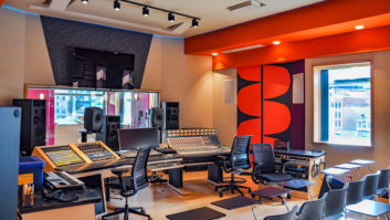
Rear view of mix room with fabric-covered absorber panel between QRD diffusers and projector portal
STEP THREE: TAMING THE LION
Many phenomena that determine a room’s sound quality happen in the low frequencies, up to around 500 Hz. (Some say 300 Hz.) The first thing that caught my eye on the waterfall plot was a particularly long decay at 40 Hz and reflected in the third-octave RT60 graph. So my first order of business was to tame that.
The usual approach here would be to “throw in some bass traps.” But rather than apply this indiscriminate fix, I wanted to put my data to work. To tame the long 40Hz decay, a bass trap would need to be around seven feet deep (a quarter-wavelength of 40 Hz). Not practical. I could also use polycylindrical absorbers (a curved shape that looks like a concrete-form tube), which would also add diffusion to the room, but a polycylindrical absorber that’s effective at 40 Hz would be far too big for this room. Alternatively, I could use diaphragmatic or panel resonators (a panel over a sealed cavity), but they require more depth to get to 40 Hz than I can afford.
This leaves my favorite LF absorber, a Helmholtz resonator that uses the volume (not the specific dimensions) of a sealed box, the size of a port cut in the face and the depth of the port to tune it to a particular frequency. Enclosure dimensions can be varied to fit the space, and port size adjusted to tune it to the desired center frequency.
So taming the room’s wild low frequencies required building a series of ¾-inch plywood boxes into the face of the speaker wall and flush to it. Each box was tuned to one of the frequencies that had a long decay or other problem by adjusting its port size. For ease of construction, the boxes had the same internal dimensions; I then calculated the resonators’ center frequency as I nudged the port dimensions. For larger LF problems, multiple Helmholtz resonators tuned to those frequencies were installed.
STEP FOUR: SPREAD THE GOOD STUFF
The most important thing in making a room sound good is diffusion. It promotes sonic consistency throughout the space; breaks up early reflections that smear the sound and degrade the localization; and helps deal with those flutter echoes we created when we specified a rectangular room. Diffusion preserves sonic energy and spreads it around, while absorption reduces energy with little spreading. In simplistic terms, diffusion affects the room’s sound while absorption affects the RT60.
There are a number of different diffusers that can be employed: polycylindricals, geometric irregularities and RPG’s Skyline and—my personal favorite—Quadratic Residue Diffusors (QRDs). Diffusers are first placed in the critical reflection points on the room surfaces. And just where might that be? The primary mixer position is our most important listening point. Now catalog the surfaces—left wall, right wall, back wall and ceiling.
Sitting at the primary mixing position, there’s a point on each surface where if you place a mirror, you’ll see one of the speakers. This is a critical reflection point, where the initial sound reflects back to the mixer, arriving delayed from the direct sound due to the increased distance traveled. In a film room with three front speakers, there are three of these critical reflection points on each of the four surfaces. Don’t worry about the surround speakers; they operate at a lower level, with secondary program material.
Now draw an imaginary rectangle on each surface that includes all of the three points. Expand each rectangle to accommodate all the positions that the mixer might listen from—i.e., center console, left console, right console, pushed back from the console. Now expand each rectangle again to accommodate the critical reflection points for the client area and the listening positions there. Finally, expand the area so that it will hold your chosen diffusers without cutting any to fit. That’s where you put your diffusers for that surface.
Doing this for the ceiling can be difficult so we installed a suspended T-bar ceiling with 2×2-foot openings. This simplified adding the acoustic elements to the ceiling. We also painted the T-bar frame and everything in it black to minimize light flare from the projector and make the ceiling “disappear.”
The primary diffusion element for the ceiling was thermoformed plastic QRDs, placed to cover the critical reflection points. Using the T-bar ceiling made it easy to get proper positioning. Additional diffusion was installed using plastic polycylindricals that fit in the openings.
STEP FIVE: SUCK IT UP
I prefer the sound source to emanate from what I call “audio black,” where the sound comes from a point source rather than an indistinct blob of a position. To minimize the diffractions and reflections that smear this desired point source (not to mention the reflections off the back of the screen), the speaker wall was covered with Owens Corning SelectSound Black Acoustic Blanket that was two inches thick. Many studios use 1-inch Fiberglas absorbent (commonly Owens Corning 703 rigid Fiberglas panels), so why two inches?
Just like bass traps, the depth of any absorber determines its cut-off frequency, where the thickness equals a quarter-wavelength and they act like lowpass filters. Theoretically, the lowest frequency a 1-inch-thick absorber can tackle is around 3,378 Hz. (For absorbers of varying thickness, I consider the cut-off frequency to be determined by the thinnest part.) Two-inch material lowers the cut-off to approximately 1,689 Hz, making it a more effective absorber. But there are other factors at play here, so it’s better to see what actual measurements reveal.
The published data for SelectSound states the sound absorption coefficient for 2-inch material is 0.80 at the 250Hz band and 1.0 through the 500 to 4k Hz bands. It drops to 0.27 around 125 Hz.
The sound-absorption coefficient of 1-inch SelectSound never gets to 1, peaking at 0.91 at 2,000 Hz, with the frequency response knee around 1 kHz. This leaves frequencies from around 300 Hz (the top of the range where Helmholtz resonators are practical to use) to 1 kHz minimally affected by any absorption, and therefore essentially untreated. This can color the response of the room.
The thicker material has a smoother response that dovetails nicely with the range of the resonators. Thus, the absorbent combination (Fiberglas panels and resonators) does its job, with no frequency bands left behind. And smooth and neutral is the goal here. The Helmholtz resonators handle the lows, the 2-inch absorbers the rest.
But how much absorptive material should be used, and where should it be placed? I wanted to bring the RT60 down but didn’t want to over-dampen the room, making it uncomfortably dead. A few calculations gave an idea of how much to use, and we installed the first panel on the back wall above the diffusers. Rigid Fiberglas can shed fibers, so all of the absorbent panels in the room were covered in a fire-rated cloth with an acoustically transparent, tight weave. Panels were also installed along the length of each sidewall. This also helped reduce any side-to-side reflections at the console and client positions, aided by the blackout curtains over the windows. Finally, some uncommitted T-bar openings were filled with black cloth–covered, 2-inch rigid Fiberglas squares to absorb console reflections. The remaining openings were filled with black ceiling tiles.
STEP SIX: FINAL TOUCHES
With the acoustic treatments in; the console installed; and the amps, speakers, perforated screen and projector installed, Dolby techs came to perform an initial tuning. It was time for the final check: another room analysis. The ETC showed that the reflections were nicely distributed in a random pattern, well below the level of the direct sound. The waterfall plot showed a uniform decay across the frequency spectrum. The frequency response was a bit bumpier than I would have liked, but nothing that final room tuning couldn’t easily handle. The RT60 was right where I wanted it—not too live, not too dead.
But the final and most important test remained: the trial by ear. Massey brought in a reel or two of his recent work, hit the Play button and turned to the screen. Minutes later, the playback ended and there was a relaxed smile on his face. This was all I needed to know. He later did some mixing in his new roo, and listened to it in the Cary Grant Theatre. He was still smiling so I knew I had done my work well.
Early construction view of mix room shows Perform Wall block construction.
PERFORM WALL—WHAT THE HECK IS THAT?
Perform Wall is a very “green” construction material comprising large blocks made from recycled polystyrene, cement and water. While they look like large concrete blocks, they’re actually surprisingly light concrete forms that are left in place after the concrete is poured.
To construct a wall, the Perform Wall units are stacked, rebar is installed in the blocks’ voids and concrete is poured into the openings. This results in a monolithic, concrete-reinforced wall that provides excellent structural strength, thermal insulation and earthquake integrity, as well as significant sound attenuation. The Perform Wall system also provides extreme resistance to fire, wind, mildew and black mold.
The walls can be laid out curved, and the blocks can be easily formed into any shape by cutting or rasping them using standard construction tools. This allows almost limitless design possibilities.
Plumbing, electrical and other utilities should be installed before the concrete fill is poured, as in normal construction. However, within certain limits, it’s also possible to add utilities after the pour by cutting channels and notches in the Perform Wall block to accommodate the required infrastructure.
As Perform Wall blocks have cement in them, standard construction adhesives can be used to attach common materials like gypsum board, stucco, plaster, brick, stone or tile.
Perform Wall is approved by the City of Los Angeles Department of Building Safety, certified by Underwriters Laboratory and carries the Energy Star logo.
Bruce Black operates MediaRooms Technology, an acoustics/studio design firm based in Southern California.