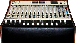
In geekville, there are those pesky pieces of gear that don’t want to be fixed, and then, “Eureka!” — the mystery is solved. A year ago, a 12-input, 1970s-era Raindirk portable recording desk (pictured at right) arrived from an owner willing to invest in both the shipping and repair charges. I usually discourage such things, but some combination of temporary insanity and a piqued curiosity made me say, “Yes.” I never envisioned it would take a whole year, but hopefully, desk and owner will be happily reunited by the time you read this.
This particular Raindirk is a rare and curious beastie, a hybrid of discrete and op amp circuitry designed into a location mixer capable of both AC and battery operation. The owner had upgraded the op amps and meticulously replaced all of the electrolytic caps with Nichicon’s Muse Series. Then I came in to tame the quirks. The initial job was as simple as fixing dead channels — the few broken wires on each channel strip were easier to find than the funky pins on the Penny & Giles faders.
MYSTERY ONE: TRANSMITTER OR AUDIO DEVICE?
One obstacle to upgrading op amps is that their extended high-frequency response at high gain settings can emphasize other shortcomings in the design, like the circuit board layout or power distribution. Troubleshooting Mystery One’s asymmetrical headroom issues revealed oscillation when cranking the gain and/or boosting the HF EQ. The typical approach to solving oscillation is adding power supply bypass capacitors (0.1 uF to 10 uF, and sometimes both) at the IC sockets, which reduced the problem but didn’t eliminate it.
As the console was designed for battery operation, the power supply is single-ended — just ± (ground) rails — which is typical in Class-A circuitry like the Neve 1073 and 1272 modules. To work in this environment, op amps must be biased halfway between the supply rails with a matched pair of resistors (Fig. 1) configured to make a voltage divider. Checking each channel’s behavior at clipping revealed an inclination to oscillate that wasn’t due to resistor tolerance. In fact, the console has a mix of 2- and 5-percent resistors, and — judging by the range of values found — some were hand-selected.
The two op amps in each channel strip were responsible for the mic line gain trim and the EQ network. As such, they were designed to drive a 600-ohm load at the insert point, which was still very common at that time. The original dual op amp, a 14-pin TBA231 (UA739), was not really capable of driving a 600-ohm load, so it was buffered by a transistor configured as an emitter follower for current gain (power) rather than for voltage gain.
The transistor was now unnecessary — and part of the headroom/oscillation problem — so it was removed and replaced with a piece of copper that became a convenient place to hook an oscilloscope probe. I also chose to reduce the op amp’s gain by just enough to ensure stability, even with “wild” EQ settings.
MYSTERY TWO: THE LOW CEILING
Under real-world conditions, the console still seemed to be plagued by what turned out to be two additional and completely separate headroom issues. For this reason, I’d been running the console’s gain structure to favor headroom over noise, making up gain with a compressor/limiter after the main stereo outputs. The first problem was “simply” an intermittent section in the power supply.
The console runs on 36 volts — or three 12V car batteries in series — which, when divided in half (for the op amps), simulates the more typical bipolar configuration of ±18V. Inside the power supply chassis were three supplies, two of which were wired in series to make the 36 volts, the other unused. Somewhere in transit, a wire had been weakened and eventually broke loose, reducing the 36V supply to 24V and resulting in a 3.5dB headroom loss.
MYSTERY THREE: SLOW ON THE FAST CURVES
Used in session, the Raindirk behaved relatively well, the talkback being more useful than the EQ. (The midrange EQ bandwidth was far too narrow, and the starting point of the HF shelf seemed too low.) Again, there seemed to be a headroom issue at high frequencies, which was most noticeable on sibilance when trying to add a little “air.” Again, I solved this problem using external EQ on the mix bus.
THE EQ DETOUR
While modifying the EQ wasn’t part of the original assignment, it is one of the key reasons for choosing a console and one reason I investigated the possibility of tweaking. As the console’s peak program meters (PPM) were a bit flakey, I initially chose to monitor the console’s output using the VU meters on an Otari MTR-10 2-track.
Boosting the treble pot all the way and sweeping a sine wave oscillator yielded a “bump” around 7 kHz, a clue that confirmed what I had heard in-session. This seemed odd because there were no “bandwidth-related” components in the treble-EQ circuit — at least I didn’t see any on the various schematics, all of which were similar to the actual circuit but never completely accurate.
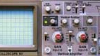
Switching to a square wave oscillator and monitoring the channel strip and the mix bus via ‘scope revealed another clue: much better square waves on the former compared to the latter. Boosting the treble exacerbated the problem to the point where pursuit of any HF EQ mods was temporarily abandoned. I could at least explore the mid-band EQ.
Note: A perfect square wave is so “vertically fast” (the rise time) as to be nearly invisible, leaving only the top and bottom “horizontal lines” representing the fundamental. As the rise time is at least 10× the fundamental, it’s possible to “see” EQ and even more subtle anomalies, like the effect of cable capacitance on a high-impedance circuit or amplifier slew-limiting at high-level swings. A 1kHz square wave is a useful test signal, albeit hardly one that you’d want to listen to.
CALL IN THE PARAMETRICS
Thanks to George Massenburg and Burgess MacNeil, we now take for granted equalizers that have the ability to continuously sweep frequencies. Previously, multifrequency EQs like Pultec and Neve required switches and inductors (resonant coils of wire) in addition to resistor-capacitor (RC) networks. Many op amps are required to achieve Massenburg and MacNeil’s parametric EQ magic. By contrast, the Raindirk has only one op amp available, so its designers chose to use inductors for the low- and mid frequency EQ. The mid inductor was particularly elaborate in that it had “taps” for each frequency. Similar inductors are available from Sowter (www.sowter.co.uk) for about $80 each.
I knew that the solution to the Raindirk’s narrow mid Q had to be simple or it wasn’t going to happen. If easy, then it might be possible to modify the front panel with a pot and/or switch. As all of the taps on the inductor were in series, my instinct was to put a resistor across the whole thing, which worked out nicely. (See Fig. 2.)
MYSTERY REDUX: A-HA!
Back to the HF equalizer and the treble-related headroom issue. I was simultaneously monitoring the channel strip module and the mix-bus signals. The square wave revealed a severe “speed” limitation that turned into slew-limiting as the signal approached its maximum peak-to-peak level. With little accurate documentation available, it was necessary to open a cable harness to trace the signal flow.
The Raindirk’s two aux-return modules contain mono versions of the ADR model 760R, a FET-based signal processor known as the Compex limiter (because the rack version includes an expander). On each module, a switch routes the Compex to either the stereo bus or to a patch point on the console’s rear panel. Choosing the latter solved the “speed” issue, indicating that the problem was in the 760R’s circuitry — specifically, its output amplifier, which is used even when the processing is bypassed.
MISCHIEF MANAGED
Once the problem was localized, I blew up that portion of the schematic, surveying all of the possible causes. I lifted one cap sitting on the output (used to keep RF from entering the feedback loop). When it did nothing, I had my assistant try the 3.3 picoFarad (pF) cap (see Fig. 3); it’s between the base and the collector of that transistor and guess what? The “Eureka” moment! Two caps in that application are not likely to fail. Looking closely at the pulled cap, it was labeled 332, which is 33 plus two zeros, or 3,300 pF! To be off by a factor of 1,000, obviously a mistake was made during the assembly process that only took some 30-plus years to troubleshoot.
For more geek fun, visit Eddie online at www.tangible-technology.com.