Illustration: Kristen Schmitigal
The inspiration to do-it-yourself has many muses, from purely creative to über-frugal. Like all “sound” investments, the rewards come gradually at first. If you want to jump onto the geek merry-go-round — without it breaking down or you getting flung off — it’s better to start within your comfort level and get results rather than get lost, frustrated and stuck with a box of parts. Let’s consider a few options.
Wire Monkey
Making cables is a good entry-level task so long as you accept that the first attempts are just for practice. Look at how other cables are made and do your best to emulate them. A wiring project is geek therapy: advancement through repetition and a great exercise in honing fine-motor skills.
After stripping insulation and tinning (applying solder to the wires and the connector), the key to good wiring technique is to butt the insulation right up to the solder connection and not have any exposed bare wire (to avoid short circuits). The amount of insulated wire from the end of the cable’s outer jacket to the connection should be as generous as circumstances allow; a common mistake is cutting these too short. Bare shields should be sleeved with either Teflon or shrink tubing. Larger-diameter shrink is also used to overlap the junction from the outer jacket to the individual wires — at least ¼-inch on each side, ½-inch total.
Kit and Kaboodle
Kit building is equally therapeutic and lets someone without an electrical engineering degree build something useful. In addition to fine-motor skills, “growth” can be realized in the simpler things, like using a multimeter or the ability to recover from an accidental resistor spill, thanks to an understanding of the resistor color code. The ABCs of electronics include learning to identify and correctly orient electronic components into their designated positions, and correlating physical parts with their schematic symbols. Master these basics, and you’re ready to move on to schematics.
A great first-choice project is a fuzz box because many circuits are variations of a similar diode-clipping theme. Earlier designs use germanium diodes (still available), followed by silicon diodes and even LEDs. Each diode type has a sound and each sound is typically equalized to remove some of the high-frequency edginess and LF mud that comes with “super-crunch.”
After picking a circuit you want to learn more about, I recommend drawing the schematic as an exercise. Do the same for other fuzz box schematics, making a point to lay out the major components — such as op amps — in the same place to make comparisons easier, with pattern recognition being the goal. Once the circuit similarities are obvious (the forest), component differences will reveal themselves (the trees), and from there the natural progression is to build and listen and tinker and listen until you understand how component values change the sound and which sound is your sound.
Bread and Board
Buying a kit might be the easiest way to get started, but if you’ve stumbled upon some similar circuits and want to experiment before committing — and not have to mess with soldering, unsoldering and re-soldering — a solder-less breadboard makes the job easier. Let’s continue with the fuzz box theme using an op amp. Once the circuit is up and running, the breadboard becomes a playground where you can easily swap diodes and capacitors for ease of experimentation.
At the top and the bottom of the breadboard are two horizontal rows of red and blue connections that are typically used for power and ground distribution. In between are two vertical columns of five connections each, separated by a “moat” that can be straddled by an IC. Poke the components in the holes, use solid wire jumpers to make the remaining connections and you’re ready to rock.
Between solderless breadboard and printed circuit boards are prototype boards (plated through-holes to make soldering easier) and perf board (a perforated board without any copper or traces). Hole spacing is typically one-tenth of an inch to accommodate an IC’s pin spacing. RadioShack has the most accessible options, which are all made on a phenolic-base material. Those boards can easily break when stressed. However, that same trait becomes useful when cutting a large board down to size — the board easily snaps along the grid.
Between solderless breadboard and printed circuit boards are prototype boards (plated through-holes to make soldering easier) and perf board (a perforated board without any copper or traces). Hole spacing is typically one-tenth of an inch to accommodate an IC’s pin spacing. RadioShack has the most accessible options, which are all made on a phenolic-base material. Those boards can easily break when stressed. However, that same trait becomes useful when cutting a large board down to size — the board easily snaps along the grid.
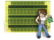
Darren Hovsepian — president of DH Labs, a company specializing in high-end cabling — created the D-4 Proto Board to try out op amps and some application-specific audio ICs. This $5 prototype board allows a seamless transition from the solderless breadboard. While it can be used for any simple circuit application, it is intended for op amps. The three large horizontal traces are for bipolar power distribution, plus rail (common-neg rail). Like the solderless breadboard, the op amp straddles the horizontal center path/ground bus. Each vertical trace can connect multiple parts to each op amp pin.
High-quality circuit boards are made of a Fiberglas-epoxy material. These are typically green, but also come in red, blue and black. Suppliers of generic boards include DH Labs, Electronics Plus, Ocean State Electronics and SchmartBoards.
Building a Prototype
Once you are confident that your circuit achieves the goal, be sure to annotate the original schematic, or draw a new one, before constructing the real deal. If you have a prefab kit, you can hope that all of your variations will fit into the existing holes. While it’s easier now than ever to make a professional-looking project inside and out, I highly recommend first building a prototype to get all of the kinks out. Live with what you’ve built for a while before making it beautiful.
Be curious enough to tinker and you will master the basics. Keep up the tinkering and the ultimate reward is the ability to think “circuits,” like thinking in another language, and eventually derive your own custom circuits from a mental library of “stuff that does this or that.”
For more Eddie Ciletti, visitwww.tangible-technology.com.