My focus this month is on the AKG C-414, a venerable studio condenser mic that has about as many permutations as the Universal Audio 1176. At first glance, this might appear to be a history of the 414 when it’s really about understanding the technology, the mic’s inner workings and trying to keep it working.
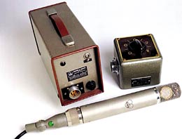
The modern C-414 hails from the original C-12, shown; the C-12A that followed it used a Nuvistor tube and debuted the familiar boxy body shape associated with the later 414 Series.
This story started with a collection of broken mics waiting for a quiet, undistracted moment. The sad thing about many of these specimens was their physical condition — AKG 414s with their head assemblies and grilles snapped off, or dented Neumann U87s with broken switches, and filthy and punctured capsules. So, at the very least, use a windscreen and keep your mics out of harm’s way (and/or flailing drumsticks) or use an out-of-the-way mic like the indestructible Josephson e22S.
CHARGE IT UP
Condenser mics start with a polarized capsule, meaning that a charge is put on the capsule that will vary with changes in sound pressure. The impedance of the network around the capsule is in the gig-ohm region, making what little signal there is weak and vulnerable. This voltage from the capsule is fed to a “head” amplifier that, at minimum, will convert the impedance from gig-ohms to k-ohms. Most amplifiers will contribute voltage gain (make the signal bigger) and current gain (make the signal stronger; aka, more power). One variation is detailed below.
The 414’s lineage begins with the CK-12 capsule and the C-12 microphone (1953 to 1963). The C-12 uses one-half of a 6072 dual-triode configured as voltage amplifier (common cathode). The other half of the 6072 was reserved for the C-24, the stereo version of the C-12. In the late 1950s, Neumann stopped making the U47 and U48 for Telefunken, so AKG was approached to make similar products: the Telefunken Ela M 250 and Ela M 251. Aside from the obvious polar pattern options and a different outside housing, they are at heart a C-12 with a few circuit variations. (See Figs. 1 and 2.)

Figure 1: AKG C-12 schematic with Ela M parts and output circuit path (common cathode) highlighted
The C-12 has a grounded cathode, while the 250/251 E versions use the same 6072 but in series, where the cathode is a resistor in parallel with a capacitor. The non-“E” broadcast versions of the Ela M 250/251, as well as the Neumann M269, use an AC-701. (The U67 uses an EF-86/6267, a pentode wired as a triode. The AC-701 is a miniature triode with wires instead of rigid legs.)
NEW VISTAS
In 1959, RCA introduced the Nuvistor — a transistor-sized vacuum tube — and by 1962, AKG had incorporated it into the C-12A, a new mic that debuted the now-familiar “414” body shape. Because there was no room in the C-12A for an output transformer (it’s located in the power supply), the amplifier’s output impedance must be lower to drive the long mic-to-power supply cable and the extra capacitance created. For this reason, the little 7586 Nuvistor is configured as a cathode follower — a current amplifier — rather than the common cathode circuit in the C-12 and Ela M 250/251. [Note: Both the 7586 and its lower-gain cousin, the 6CW4, have a 6.3-volt filament that draws 135 milliamps.]
I first encountered the C-12A in 1978 while working at Bearsville Studios in upstate New York. While the C-12A was not as highly regarded as the C-12, I recognized that the C-12A was special. (I was careful to hide it in a drum kit — under a pair of rack toms and set to omni — so it wouldn’t get smacked.)
MOD WORLD
In 1968, Neumann published a document detailing modifications for the U47 and U48, substituting the VF-14 with another Nuvistor, the 13CW4 (the 13-volt version of the 6CW4), chosen for its low heater current of 60 milliamps as compared with the 6CW4’s 135mA consumption. The stock U47/U48 consumed a mere 40 mA of current, so “minor mods” to the power supply and mic were all that were required to meet the new, slightly higher current demand. Of course, nothing sounds quite like a VF-14.
Figure 2: AKG C-12A schematic with output path (cathode follower) highlighted
AKG then took advantage of the earliest replacement for the vacuum tube — a field effect transistor — to make the C-412 and C-414 possible. (They look identical to the C-12A; the lower, “unfamiliar” section of the mic is a 6-pin connector of which only three pins are used, thanks to the development and success of phantom power. One special version, the C-414E1, was phantom-powered but took advantage of the additional pins for remote pattern control.) The external power supply was eliminated. Most of the active and passive devices were successfully miniaturized. There was now room for relocating the pattern, highpass and pad switches into the mic body. “Iron” was the final obstacle to the process. The U47’s output transformer is about the size of a 414 body, sans grille, and things have been shrinking ever since. Transformers are already harder to drive and easier to saturate at low frequencies; miniaturization makes saturation easier or more challenging to overcome.
When the C-12A was in production, AKG was already aware of how subsonic information challenged the output circuit. As mics were being moved closer to the source, even more low-frequency content was added (courtesy of the proximity effect). All of this, plus cost, drove the quest for continued circuit improvements until the transformer was eliminated by all but boutique manufacturers.
BRAIN DRAIN
Vacuum tube electronics are elegantly simple because there is typically a single gain stage and all power is derived from an external power supply. Within the mic are three networks: the capsule-polarizing voltage, the filament and plate power. With the exception of the capsule, repairs are relatively easy.
Things became more complex with the introduction of solid-state electronics and phantom power. Up until the C-12A, there was a single active device in the mic, but when the C-412 and C-414 were introduced, there were three active devices, four in the C-414EB (1977) and C-414EB-P48 (1982), and 18 in the C-414B-TL!
While 48 volts is nearly enough to polarize some capsules (the C-414 EB/P48 version), many designers chose to incorporate a switch-mode power supply within the mic to make the capsule voltage independent of variations in phantom power and amplifier demands. A switch-mode supply comprises an oscillator and voltage-multiplier circuit that can deliver the required polarizing voltage and tolerates a wide phantom supply range — from 9 to 48 volts.
There are two versions of the C-414EB: The 1977 version has a switch-mode supply and the P48 (1982) version runs exclusively on 48V phantom power. The former has a fairly simple three-device “head” and output amp on one PCB and a transformer-based switch-mode supply on the other PCB (with a single transistor).
The P48 version has a two-device headamp on one board; on the other, the highpass filter is integrated into the two-device output circuit. Whereas the C-414EB has a very conventional, nearly tube-like design, the P48 version makes use of a current-source configuration to optimize the load for the head and output amplifiers. It was a remarkably efficient mic for its time.
ONCE BITTEN
This is where I get to admit that the P48 stumped me for quite a while. It’s common knowledge that capacitors are the component most likely to fail over time. In this case, the output capacitor shorted out, bypassing the current source and making the output amp appear functional. (The two-board design that began in 1977 allows the signal between boards to be easily interrupted so that an oscillator could be injected.)
Without the current source, the output amp was drawing more than 1 mA of current, swamping the capsule-polarizing voltage and making the mic appear dead. I was thrilled to get it up and running, but embarrassed to be bitten by a stupid capacitor, even though it wasn’t the only obstacle.
Experiences like these make us smarter. At minimum, it put me on a fact-finding tour to collect all of the schematic variations. It also forced me to learn the contribution of every component until I fully understood the entire circuit.
Eddie would like to thank Pat Burns at AKG, and all of the Web’s contributors for bits and pieces of history and documentation.
