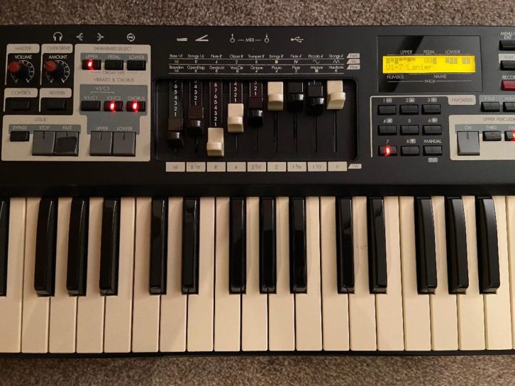
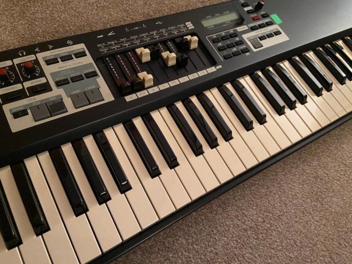
The Hammond XK-1c is a really cool, compact portable organ that emulates the classic sounds of the Hammond B3. We’ve had one on the road for about six years, and as is often the case with gear that’s on tour, it’s taken more than its fair share of bumps and bruises.
A few weeks ago, we discovered that the DC power inlet wasn’t holding the power supply connector securely. Taking a look inside the receptacle revealed that the jack had been damaged by some overly aggressive plugging and unplugging. At that particular gig, I popped it open to see if there was anything that could be done to fix it on the spot, but we didn’t have the parts on hand to do the job.
Given this day of gear that can’t be fixed in (or anywhere near) the field, I was fairly certain that we’d need to pack it up and send it to Hammond for repair. When we got home, I called the techs at Hammond and learned that the DC power jack could be replaced(!). Hammond sent a replacement power jack, and it was time to give the XK-1c some TLC. Here’s some tips if you find yourself in a similar situation.
The XK-1c is fairly service-friendly, and getting to the main PCB was the most time-consuming part of the task. Removing six screws at the top of the rear panel and four more on the bottom panel near where the Hammond name is screened allows the top panel to lift straight up.
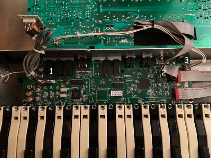
The top panel PCBs and switches are connected to the main board with one ribbon and two multipin connectors (see Fig. 2). Disconnecting these allows the top panel to be separated from the rest of the chassis.
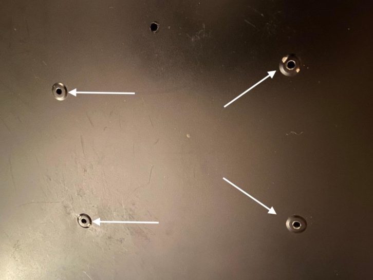
The next thing to remove is the action, which is held in place with 12 screws. They are easy to spot on the bottom panel because each of them is surrounded by a circular impression.
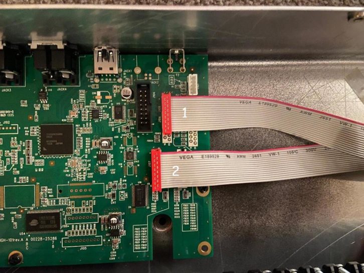
If you disconnect the two ribbon cables that connect the action to the main board (see Fig. 4), the action can be removed and set aside.
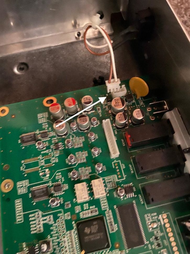
This leaves the main circuit board sitting by its lonesome in the chassis. Remove the five screws that pass through the main PCB, and disconnect the small multipin cable that runs to the power switch (see Fig. 5).
Five more screws secure the PCB to the rear panel, as do six plastic push fasteners flanking the MIDI in and out, and the Leslie 8 pin jacks; these can be gently pulled out with a fingernail.
Read more Mix Blog Live: Resurrecting an Audio Dinosaur, the Final Chapter.
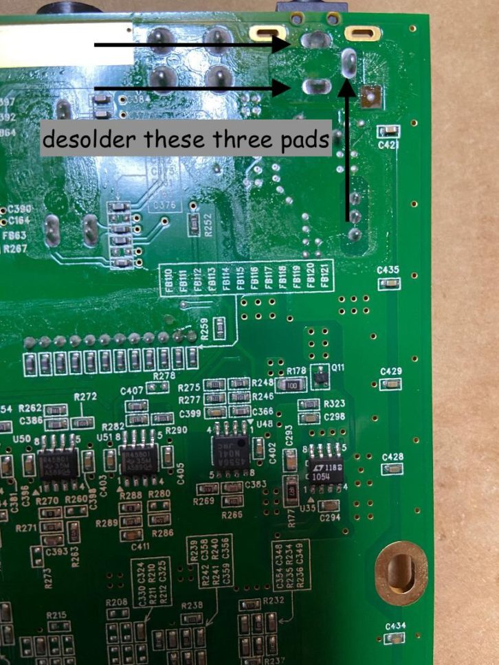
This frees up the circuit board for an easy trip to the bench, where the tricky part of the process takes place: removal of the old DC power jack. I used desoldering braid to remove the old solder, along with a bit of gentle wiggling to coax out the old jack, but you can also use a solder sucker. Once the old power jack was removed, I cleaned the contacts with a bit of contact cleaner, snapped the new jack into place and soldered it.
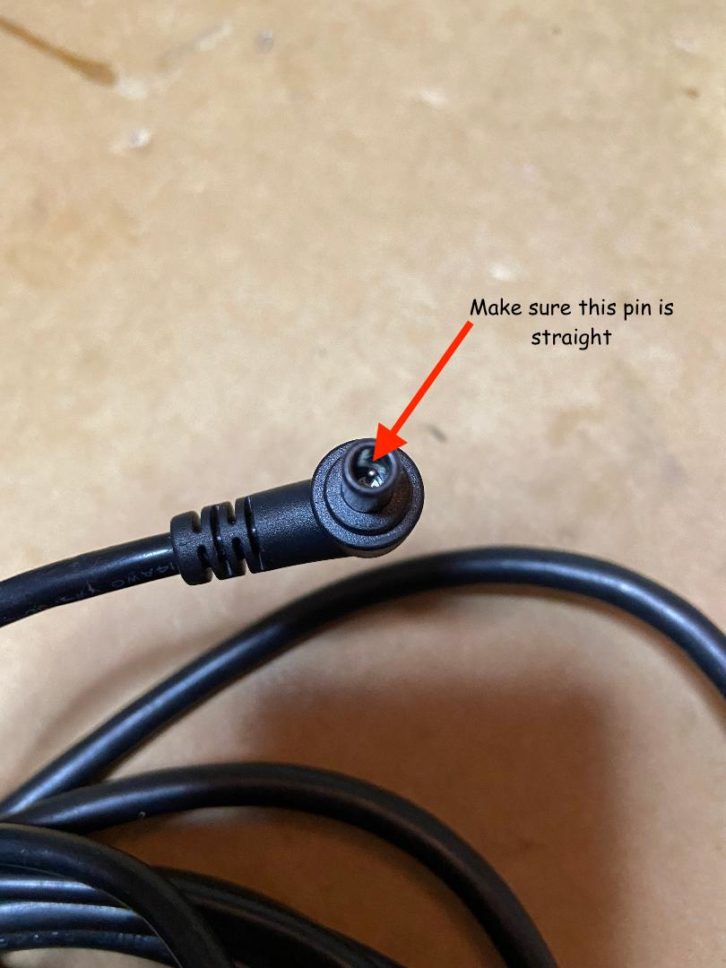
As you’d hope, reassembly was the same process in reverse, with no hitches or peculiarities. One thing that’s worth noting before you connect the power supply: check the pin inside the barrel connector to make sure it’s straight.
A little scary… but not really.