ANALOG MAINTENANCE AND UPGRADE CONSIDERATIONS
I get plenty of e-mail regarding “modifications and upgrades” to recording consoles and other pieces of audio gear. I chose those words carefully to make a point. More often than not, modifications can be as expensive as a new piece of outboard gear, or worse, a major detour into oscillation-land. Why modify a console mic preamp when there’s already a product whose designer auditioned each component for its sound, or lack of same? By contrast, the decision to upgrade should be borne from the maintenance history of the console or tape machine.
If you want to know a little more about basic maintenance, enough to make educated decisions or possibly go a little further, ya gotta be in the ballpark to see the game and ya gotta practice to play the game. So let’s find our seats and check out the opening lineup. What better way to demonstrate the process of comparative analysis than by testing a recording console or tape machine, good channel next to bad channel?
CAPACITORS: SQUARE BIZ
Geeks-in-training need to start with maintenance fundamentals, which includes familiarity with test equipment and electronic components. (A list of test gear was detailed in the May 2000 issue.)
Capacitors – the weak link in almost any aged product – are failure-prone over time, making travel for low frequencies difficult. The end result is “thin” sound.
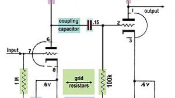
You can test for bad capacitors without pulling a module; the fastest way requires a square-wave oscillator and an oscilloscope. Fig. 1 shows a family of square waves, starting with 1a showing the 500Hz reference wave; 1b indicates the bass roll-off tilt caused by bad capacitors; and 1c shows how bass boost tilts the wave in the opposite direction. (Any midrange frequency will yield similar results.) This test is particularly useful when checking old Pultec and Neve modules or any equalizer that has switched EQ settings. Not only do you want to know that all frequency options are functional, but also that the center detente is really “flat” and that the output transformer (if applicable) is properly terminated.
Also included are snapshots of treble boost (1d) and cut (1e). All “visual effects” were produced with a shelving equalizer where the slope is a gentle 6 dB per octave. A lowpass (high-cut) filter has a much steeper slope, at least 12 dB/octave, leaving more bandwidth untouched and leaving a recognizable footprint, as seen in Fig. 1f. Notice how the rise time of the square wave is affected. The images will vary depending on the slope of the EQ curve. Boosting the midrange EQ at the same frequency as the oscillator will turn it into a near-sine wave.
MODULE ETIQUETTE
Once the bad modules reveal themselves, it’s time to find the bad caps. Be sure to mute the speakers and power down the console when removing and replacing modules. An extender card makes it easy to probe individual modules. If you don’t have that luxury, pull a few modules to clear some real estate. A schematic will help locate input and output caps – most of the time, the circuit board is silk-screened with part designations. Using a `scope probe, locate a cap at the input or output of an amplifier and check each leg for the “before and after.”
You might find that many of the same caps in each module have failed. The decision is yours to change only those that typically fail, or go the “wholesale replacement” route. Caps can fail in batches – some are more stressed than others and then some just plain suck. Once you begin to recognize them, order a quantity to have on hand when some down time opens up. Digi-Key (www.digi-key.com) is a good place to buy mass quantities.
I like to replace electrolytic inter-stage (coupling) caps with Panasonic’s HFS series, designed to withstand the abuse of switching power supplies and rated for 105 C. The difficulty with selecting replacement caps is that many were originally chosen for their small footprint, which is mostly determined by selecting (some would say compromising) voltage and capacitance values. Construction materials also affect size. The ambient temperature inside the product must also be considered. Heat shortens life, so the 105 C rating is a safer bet than the more typical 85 C.
As a rule of thumb, the power supply rail(s) should be within 70% of cap’s DC voltage rating. Quite often, caps ride the rails much closer than that (not good). For example, a 24-volt rail wants a 35-volt cap. Using one rail of a bipolar supply as reference, a 16-volt rail wants a 22.8-volt cap, which you’re not going to find. Capacitor voltage ratings are stepped – 10V, 25V, 35V – so the next highest value is a good place to start. For additional comfort margin, add the bipolar rails together, but remember that larger capacitance values and voltage ratings make bigger caps. Good, compact caps cost even more.
Yes, you can argue that different capacitor materials have a sound. Dave Hill of Crane Song once told me a story about replacing the tantalum caps in an old Neve module. Apparently, the non-tantalum replacements changed the sound of the module. Dave’s research determined that tantalum caps contributed more even-order harmonic distortion, not as clean – but pleasing.
OP AMPS
Before considering an op amp upgrade – those little ICs that contain dozens of transistors – other items are worth considering. Just as capacitor ratings are often just a few volts above the rails, many of the “affordable” consoles have power supplies running close to capacity. (Adding a fan, if none exists, is the best life-extending preventive maintenance.) “Speed” is important to sonic transparency – specified as Slew Rate, in Volts per microsecond or V/æs – but the most critical parameter is actually current consumption.
If, for example, the board is filled with hundreds of TL072 dual op amps – at 3 milliAmps (mA) per chip – there is no way you can “upgrade” to an OP275, at 5mA per chip, without putting the power supply into shock. If, on the other hand, the board is stocked with NE5532s (8mA per chip), then the OP275 is an option. See Tables 1 and 2 for dual and quad op amp comparisons, respectively. (The two parameters in Tables 1 and 2 only scratch the surface. Any op amp will behave differently when operating in a unity-gain circuit or in a high-gain application.)
GROUND ZERO
A customer once delivered a mixer to my shop after carefully desoldering the chips, adding sockets and experimenting by ear with different op amps. His techniques and intentions were good, but the end result was intermittent oscillations. Modifications have a way of revealing a product’s soft underbelly, idiosyncrasies pushed to the edge, in this case, by the op amp’s increased speed and current requirements.
There is no perfect capacitor or op amp; these are just two of many variables, all contributing to subtle variations of sonic character. Since this article is about “global restoration” and not specific to any one product, I welcome questions via e-mail ([email protected]). I encourage you to collect schematics, pop the cover to peek, probe and better know your gear. How else will you know how to ask the “right” questions?
In addition to Dave Hill at Crane Song, my thanks to: Greg Gualtieri at Pendulum Audio and Dan Kennedy at Great River Electronics for their input. Next class: op amp upgrades to the UREI LA-4 limiter, plus power and ground distribution improvements to the Trident series 65 console.
BUILDING A BIGGER NEVE
Some time ago, we at Ocean Studios Burbank began looking for a large-frame vintage Neve console as the centerpiece for our high-end tracking room. I have been collecting vintage gear since the `70s, but finding a large 80 Series Neve – particularly in good condition – is difficult. Eventually, we purchased an unmodified large-frame Neve loaded with 1081 modules. Then, things really became insane.
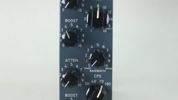
The console originally had 32 inputs and 24 monitor returns. That configuration may have been adequate in 1974 but isn’t very big by modern standards. We wanted to offer the vintage Neve sound with the size and conveniences of a newer board. We imagined an expansion to 48 (4-band) 1081s and eight (3-band) 1073s. The monitor section would feature 32 channels with 3-band EQ and 32 half-width P&G faders. The patching system would be no less comprehensive, with a 1,680-point, 11/44-inch TRS patchbay.
When expanding an older Neve, it’s pretty standard to buy two boards and join them together, but we decided to just make this one bigger from scratch. We began by buying and dismantling two extra Neve consoles for parts to expand our frame to a whopping 14.5 feet – not including the patchbay. We removed the existing 11/44-inch by 11/44-inch copper ground bar, as connecting two separate ground bars is a typical source of trouble when joining two boards. We installed a single 1-inch-wide by 11/44-inch- thick copper ground bar running the length of the console.
After making space for additional 1081 modules, we didn’t have space for even a small 28-inch TRS bay in the original location at the left side of the board, so we decided on a remote patchbay. Unfortunately, the wire looms in the existing bay were too short to reach the new location on the left side of the control room.
After extensive research and repeated blind listening tests, we came to a number of conclusions. Every connector in the audio path caused an audible loss of signal quality. We settled on long-frame, 11/44-inch TRS jacks, which sounded noticeably better than smaller TT jacks. For the multipins, we had EDAC custom-make silver connectors, which sounded superior to the common gold type.
We were surprised to discover the audible loss in a 30-foot run of straight wire was far less than that caused by a connector in a shorter 15-foot run of wire. The only way to make our console sound its best with a remote patchbay was to bite the bullet and rewire, eliminating any additional connectors in series with the patchbay.
So we pulled out all the existing wire and rewired the entire console with the most consistently pleasant sounding wire available, which was Canford Audio FST – the equivalent to the N.E.K. wire originally used in Neve consoles. (N.E.K. was bought by current manufacturer Draka-Cardinal, distributed by Canford Audio). This provided a straight, uninterrupted connection with the TRS patchbay. No one made a patchbay as big as we wanted, so Audio Accessories custom-built 15 bays for our 4-foot-wide, 1,680-point TRS patchbay.
Extra buses were installed so all 56 input strips could reach the mix bus along with the 32 monitors. For ease of use, we wired in provisions for automated EQ switching, insert switching, fader automation, a DK Audio phase and peak meter, expanded sends and cues and a 3-band EQ in the monitor section.
Once the audio portion was under control, we began working on re-creating the board’s original look and feel. After numerous trips to perfectly capable finishing shops, seeking the exact shade of RAF Blue-Gray with the correct gloss and finish, we discovered that the original painting process is now illegal in the United States. Apparently, it was as effective in polluting the air as it was in covering metal panels. We finally found a UK supplier that could perfectly match the original finish.
All knobs and switches are of the Marconi type found on the original board, so when you grab one of those huge knobs, you know you’ve got a Neve in your hand. Console silkscreen labels were re-created from scans of the original panels rather than picking a typeface that was just close, so everything looks and feels like it just left the factory.
Special thanks to consultants Eddie Delena, James Guthrie, Dave Hecht, Rob Jacobs and Phil Kaffel, as well as the Ocean team of Geoff Tanner, Stacey Dodds, Robert Breen and Deval Day.