More and more, the recording studio environment is becoming one of plug-ins replacing outboard gear. I know several engineers who are mixing inside the box and forgoing the use of mixing consoles. As an extension of that, many of my room-tuning clients are considering how to use equalizers with their DAWs for tuning their control room monitors. Some follow the standard of using either digital or analog hardware EQs for their monitors, just as they would with a mixing console. Some have taken the approach of buying control room monitors that have digital equalization built into their amplifiers. Some are assigning plug-in equalizers to the output bus and tuning the room using an analyzer, and some are considering plug-in-automated equalization systems.
In this article, I’ll examine alternatives for digital equalization of your control room, and play a bit of the devil’s advocate by providing examples of issues to watch out for if you rely on an automatic EQ system.

KNOW YOUR OPTIONS
At the most basic level, you need to consider the consequences of moving audio from a DAW into a digital equalizer and back out into an analog amplifier. If you use the equalizer’s analog inputs, then you’re looking at three conversions to get to your monitors. For my money, the smart way to go would be to come out of the DAW digital out and into the digital input of your outboard equalizer. This way, you only have one digital conversion in the chain. In either case, sampling rate should be your primary concern; aim for a minimum sampling rate of 96kHz/24-bit. Even at this sampling rate, you are restricting the signal path going to your monitors.
Some people see a digital EQ’s inherent processing delay as a negative, but I really don’t think this is much of a problem. The amount of delay incurred in these conversions and processing hardly amounts to much more than the effect of moving your speakers back 1.5 to 2.5 feet. This delay may even be of some benefit in reconciling video delay induced from using plasma screens.
Using digital equalizers allows more room-tuning flexibility than with analog. In most cases, you have the advantage of more bands of parametric equalization to use in the process of room tuning. Some equalizers allow you to set delays and compression, and incorporate crossovers — all in the digital domain. You also have the ability to store presets, which, for instance, let you have a curve for broadcast productions, a Dolby X-curve for film mixing or a personality curve for mixing rock ‘n’ roll.
Figure 1: Response of a medium-sized DVD remixing room; measurements taken over a large area
Digital EQs can come as part of self-powered speakers, as stand-alone boxes or as plug-ins for DAWs. They are either controlled by the user (in which case, the room gets tuned by some person with an analyzer) or by a computer, what I will term automated tuning systems. The computer systems that I feel most comfortable with give the user some ability to tweak the automated tuning, allowing for some human decisions about the final outcome.
The pursuit of automated equalization seems to be a trend that is growing in this industry. For example, even a certain speaker company — which in the past has basically accused me of being “Satan’s spawn” because I used equalizers to tune its speaker systems in studios — has come out with a self-powered speaker that also contains auto-equalization.
BEFORE YOU EQ
It is important to understand what constitutes good equalization technique before turning your process over to a computer. Equalizing speakers in a room should be the icing on the cake; it should be the last thing that happens in a studio, not the first. Seventy percent of getting a good room/speaker interaction is physically finding that critical physical placement of the speakers and the listener. Simply setting up a pair of speakers in a room and believing that you can force them into alignment with equalization is a huge mistake.
Figure 2: Response of a small quality-control room; measurement mic moved through a small area
Remember that some aspects of the speaker/room interface must be treated acoustically, not with equalization. One example would be first-order reflections: The frequency response of first-order reflections mixed in with the speaker’s direct signal changes as the listener moves around the console. If fixed with equalization, then a dip in one listening position may become a peak in another listening position. Equalizing bass response also requires some specific care. If you try to fill in a large hole in the bass response with equalization, you’ll wind up cutting a lot of headroom out of your speaker system, resulting in distortion. Ideally, bass response should be within ±6dB acoustically before applying equalization.
Some auto-alignment systems solve the problem of equalizing first-order reflections by simply restricting the upper limits of the equalization that will be applied. This upper limit, depending on the manufacturer, seems to run from about 200 Hz to about 400 Hz. While audio purists believe you should never equalize high frequencies, this philosophy can restrict the system; for example, the system certainly cannot apply a Dolby X-curve if one is required. It is also important to know the resolution of the filters in the low frequencies. If the filter resolution is only a half- or third-octave, then you’re not going to get a very accurate room tuning, no matter how sophisticated the analysis computer.
Learn which types of filters are used in the equalizer you’re going to apply to your system. It is important to understand that room resonances are minimum-phase phenomena. This means that to truly correct a room resonance, you must use a second-order minimum-phase filter. A linear-phase filter is good for correcting frequency linearity inside of a speaker box or perhaps to contour an instrument or voice in a track, but will not truly correct a room/speaker problem.
Automatic EQ systems work by analyzing samples of noise played through speakers, as picked up by reference mics placed at various points in the room. Here’s where the systems vary. Some systems require several microphones spread throughout the listening position. Some use just one microphone and take samples from only one position in the room. Others use one microphone but sample several positions throughout the room, while still others test in real time as the user moves a microphone throughout the listening position. While most people seem to think it’s good to get a frequency response average within the mix position, there doesn’t seem to be a single concept as to what the best methodology is.
PUTTING THE TEST TO THE TEST
I measured one auto-equalization system in two different rooms to illustrate its effects on room response. A client of mine decided to replace his aging analog equalizers with one of these digital self-tuning systems and asked me to measure the results to make sure they maintained a good response after the changeover. One room was a medium-sized space with a freestanding 5.1 system used for remixing DVD soundtracks. The other was a small quality-control room with a smaller 5.1 system mounted into the walls. This particular automatic system uses equalization throughout the audible frequency range. There is no set upper limit on the frequencies that the equalizer will adjust, and the user can make adjustments once the auto-EQ has done its job.
Figure 1: High-frequency detail
The tuning for the room in Fig. 1 on page 34 was performed by one of the developers of the auto-equalization system. The developer’s concept is to take an average of the frequency response from a fairly large section around the console. One microphone was used to sample noise; the mic was moved live over a fairly large area throughout the mix position while pink noise was played through the speakers. The tuning for the room in Fig. 2 (also on page 34) was done by the studio engineer, along with a representative of the company that developed the auto-EQ system. For this system, the same basic measurement technique was used, but the engineer kept the microphone restricted to a much smaller space around the mixing console. The room in Fig. 2 is about half the size of the room in Fig. 1.
Let me briefly explain the charts that you are seeing. The bottom window represents the curve of the room prior to the application of equalization, with the inverted equalizer curve overlaid. The top window represents the equalized room. The blue trace in the top and bottom windows represents the frequency response. This is viewed in 48th-octave resolution. The red trace at the top of each window represents coherence and, in this instance, is an indication of the amount of reflections mixing in with the direct signal. The green line in the bottom window is the inverse curve of the equalization that the system applied. (So if the trace is above the zero line, it is actually a cut; if it is below the zero line, it is a boost.) The inverse display simply allows you to see how well the equalization fits into the room curve. I placed my mic at the center mix position as most engineers will reference to this position when listening to a finished mix.
Figure 1: Low-frequency detail
Remember that these are high-resolution shots of the room (48th-octave resolution). While I consider ±6 dB to be a quite good response, the response curves would never look smooth like you might see using 1/3-octave display. The first thing that struck me about Fig. 1 was the 6dB boost that the system applied in the high frequencies. The tweeter has a natural roll-off above 16 kHz. Although, as you can see, the system does a very nice job of taking the rolled-off tweeter and making it flat out to 20 kHz, boosting this area to get a flat frequency response is going to stress the tweeter a great deal, and most likely will result in excess noise in the system, as well as distortion. Moving lower in the frequency response, you can see that quite a few adjustments were made in the midrange. These are minor adjustments in areas where there are first-order reflections and I really don’t see how they are necessary. In the case of these reflections, as you move across the mixing console, peaks will become dips and dips become peaks, so the adjustments are not meaningful. Of particular concern to me are the boosts at 300 Hz and around 600 Hz where I measure excess energy to begin with, and a cut around 800 Hz where I measure a hole due to a first-order cancellation. In the low frequencies, the system does a nice job of not trying to fill in the large holes such as those around 100 Hz and deals with a couple of high-Q resonances quite well. What disturbs me in the very low end, though, is that the system applies a shelving boost of the frequencies below 50 Hz. This would put undue stress on the woofer and remove headroom from the speaker system.
Figure 2: High-frequency detail
Looking at Fig. 2, we see the system’s same tendency in the high frequencies to boost beyond the design capacity of the tweeter. It is also obvious that a roll-off has been inserted above 4 kHz. We must take into account that this room is being used for quality control for DVD movie soundtrack releases. In this situation, one would want the room to have a fairly flat frequency response, not a personality curve. The HF roll-off was applied by the engineer after the automatic EQ had been performed to “sweeten” the sound of the system. (Perhaps boosting the tweeter beyond its capacity made the system a bit harsh?) This sweetening will result in the engineer missing high-frequency problems, such as vocal sibilance, that need to be addressed in the post-production process. Looking lower on the chart, many small adjustments were also made to the midrange — again, something I feel is unnecessary. The system appears to do a pretty good job in the area between 60- and 500 Hz. But as in the other room, I’m amazed to see a 12dB shelf from 60 Hz on down. This results in a 10dB boost at 30 Hz — something that is completely unacceptable in a room where accuracy is the goal.
I am not saying that all of the auto-alignment systems available will perform as strangely as the examples I used; I’ve only looked at a few. But the point I’m trying to make is that completely trusting these systems, without any backup measurements, may not be prudent at this point in time.
Figure 2: Low-frequency detail
To date, I have yet to see an automatic tuning equalization system that can do as good a job as a well-trained professional. However, I am sure that these systems will continue to become more and more sophisticated. A system that gives the user extensive capabilities to override and tweak the auto-EQ adjustments could prove to be quite desirable. For the time being, my recommendation would be to find someone to help you properly set up your speaker system and address the acoustical issues. Then if you want to use an auto-equalization system, have someone perform some measurements alongside, just to make sure you don’t get yourself into too much trouble.
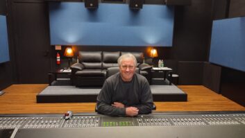
Acoustic consultant Bob Hodas has tuned more than 1,000 rooms across the world. Visit his Website at www.bobhodas.com.
WATCH:
Check out this free Webcast hosted by veteran acoustic consultant Bob Hodas.