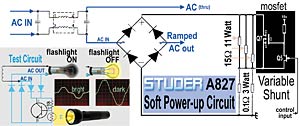
A simplified version of Studer’s soft power-up circuit. As the actual circuit is on the AC line side of the power transformers, the schematic at lower-left is a low-voltage version built for safe analysis.
A few months ago, a Studer A827 multitrack came within my depth of field. During the troubleshooting process, one of my student assistants commented that the machine didn’t seem very easy to service, to which I replied that our lack of familiarity was to blame. I then explained life in that now-rare environment, the multiroom facility.
The school where I now work part-time has two Studer A827 multitracks, one of which seemed to have a reel motor issue — the machine would play but not fast-wind. These motors are driven by a pair of amplifier cards; swapping may have moved the problem from one reel to another, but the machine would never fast-wind longer than a few seconds without stopping. All we got was an error message about a “Low Spooling Motor Voltage.”
Peter, my assistant, noticed that the rear panel of the power supply was getting very hot, which was not the case with the working machine. Another difference is that the problematic machine made a horrendous, transformer-honking sound when powered up. That, plus a faint whiff of “Cajun electronique,” was an invitation to pop open the power supply. We found a circuit board at the rear of the supply with three 15-ohm power resistors just behind the rear plate. That explained the heat source. Now the mystery was discovering why those parts were getting so hot.
The power supply for the A827 is quite the beast. Three identical power transformers have two secondary windings, each connected to a bridge rectifier feeding into a single pair of metal bus bars. Three 68,000 microFarads (µF) capacitors are connected across that bus! Studer’s design goal was a rock-steady supply that could protect the microprocessors from power line spikes and momentary brownouts. And while these machines can be had on eBay for less than $10k, I understand that the transformers are rather expensive when sold separately.
Charging 204,000 µF at the flick of a switch is a formidable obstacle, as the current required at that first instant is huge. Repeated power-ups would eventually take out a rectifier or a transformer winding. A Variac is one way of gradually applying the juice. The generic name is “auto-transformer”; it’s often used as a light dimmer and, in fact, offers the best way of powering up questionable high-current devices (such as power amps).
SOFT CELL
The board where the three hot resistors are located is home to the soft power-up circuitry. Its job is to gently ramp up the power supply. That it does so on the AC mains side — one leg of the incoming line is sent through a full-wave bridge rectifier — certainly piqued my curiosity. (Follow the darker blue lines in the figure.) Most of the time, a rectifier is used to convert AC to DC, but in this case, it’s a clever bit of electronic leverage.
To confirm that the circuit worked the way I thought it did, I built a low-voltage version for evaluation. (See the insert within the figure.) I chose a transformer with a 6.3VAC secondary driving a standard Type-47 lamp. The diodes in the test circuit (in turquoise) may look different from Studer’s “bridge” configuration, but I made that choice to show variations in the schematic arts.
TESTING E-B-C
Diodes are semiconductors. They conduct in one direction only and must see a “load” to do so. Enter the transistor in the test circuit (also a semiconductor), a generic NPN in a TO-220 case. Clockwise from top, its C-B-E pinout is connected as follows: The collector-to-base resistor turns the transistor “on,” but when the flashlight is on, the photoresistor sees the light and pulls the base to ground. The current path is from the positive output of the bridge through the collector-emitter junction to the negative side of the bridge.
The transistor acts like a variable resistor, as determined by the way that the base (input) is biased. When the base is pulled toward the collector, current flows, the transistor is full “on” (saturated) and the collector-emitter junction looks like a short circuit (zero ohms, like a piece of wire). When the base is pulled toward the emitter, no current flows and the collector-emitter junction looks like an open circuit (no resistance). In a circuit designed for audio, the transistor is biased between these two states.
The test circuit was designed to turn the lamp on when the room is dark. The transistor is biased full-on and the full current flows through the bridge. When the flashlight is on — simulating a brightly lit room — no current flows through the bridge and the lamp is off. What you see on the ‘scope is the portion of the sine wave through which the diodes are conducting. Because there is a 0.6-volt drop across a silicon-diode junction, there will always be a little glitch at the crossover point.
REALITY SHOW
In the Studer circuit, the DC side of the bridge can be divided into three networks: two that are passive and one active. Three 15-ohm resistors are in parallel (network 1) and in series with the two 0.1-ohm resistors (network 2). Their equivalent resistance is 5 ohms and 0.05 ohms, respectively. The total series resistance is 5.05 ohms.
Q7, the IRFP250 power MOSFET (shown on the right of the figure), is the active part of the network. Based on the signal applied to the control input, it acts as variable shunt. Under normal circumstances, the MOSFET should be off when powered up, and the 5-ohm network takes the heat during that very brief moment while the caps on the other side of the transformer are being charged for the first time. Then the MOSFET takes the load off the resistors. It has an “on” resistance of 0.085 ohms, a max current of 30 amps and dissipates 190 watts!
When the discolored area of the PCB was found, where the MOSFET and its FET driver are located, we didn’t bother to test anything. We pulled the parts and contacted Studer to request a cross-reference for the obsolete Q5, the drive FET. As the reel motor and soft power boards had some common components, I compiled a parts list and ordered everything through Mouser Electronics. When the parts arrived, we cleaned things up and installed Q5 and Q7, and replaced a capacitor that looked like it had been overheated. Not only was that horrible turn-on grunt gone, but now the reel motors worked.
HINDSIGHT
The information so far was collected before and after the fact. I say this because the damage was so obvious that we didn’t bother to test the suspect components — or keep them. I don’t know exactly what caused the failure, but now I suspect that the driver FET was shorted, causing the MOSFET to work in reverse. The three resistors valiantly allowed the machine to stay on, but it sagged during the high-current demand of fast-wind operation.
Meanwhile, if you own this machine or are thinking about it, be sure to reseat all of the ribbon connectors as there does not seem to be enough friction to keep them secure. When time permits, my plan is to replace them all, but in the meantime, hot glue works well and is easily removed.
CIRCUIT VARIATIONS
Surprisingly, other “audio appliances” find novel uses for the diode bridge. Studer-Revox used it early on as part of its capstan motor-speed control network. The EMT 156 and Neve 2254 dynamics processors use a diode bridge as a gain-control element, as does the Neve 33609. I’ll be exploring these circuits in 2007. Tout chaud!
Eddie would like to thank Peter Bregman and Colin McArdell for their inspiration and assistance, plus Steve Price and Ron Bloomgren for the earplug tip.
‘Tis the Season
Back-scratchers and slippers are nice gift ideas, but here’s a stocking stuffer you can use year-round — and it will pay off in better hearing health. I now own a pair of custom -15dB earplugs from Earmold Design Inc. (www.800ediminn.com) that make my world a little more peaceful. The procedure began with a hearing test and some magic goop that dried in five minutes, creating exact molds of my ear canals. The molds were then replicated and “drilled” to accept acoustic attenuators or in-ear monitors drivers. Now I can grind coffee, mow the lawn and listen to my kids screaming without being driven out of my mind — all while saving my hearing for more critical jobs.
The earplugs really enhanced my enjoyment of a Lyle Lovett concert at the State Theater here in the Twin Cities. The EDI earplugs sounded way better than going “plug-less.” Compared to the off-the-shelf variety (or a wad of tissue), these custom plugs let you hear everything, only softer. High frequencies are right there where they should be. There’s none of that underwater, disconnected-from-reality feeling.
— Eddie Ciletti.