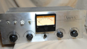
When last we left my Ampex 351 Audio Dinosaur, I had installed a newly rebuilt power supply, ensuring that all sections of the 351 were receiving clean, stable power with the correct voltages. Confident that the engine was now tuned up, I was ready to turn my attention to the audio circuitry.
The record level and playback level pots on the front panel were a bit scratchy when adjusted, so I decided to clean them. These potentiometers are sealed but (unlike similar modern components built to be casually tossed into the trash) were constructed so that they could be disassembled, cleaned and reassembled. What a concept!
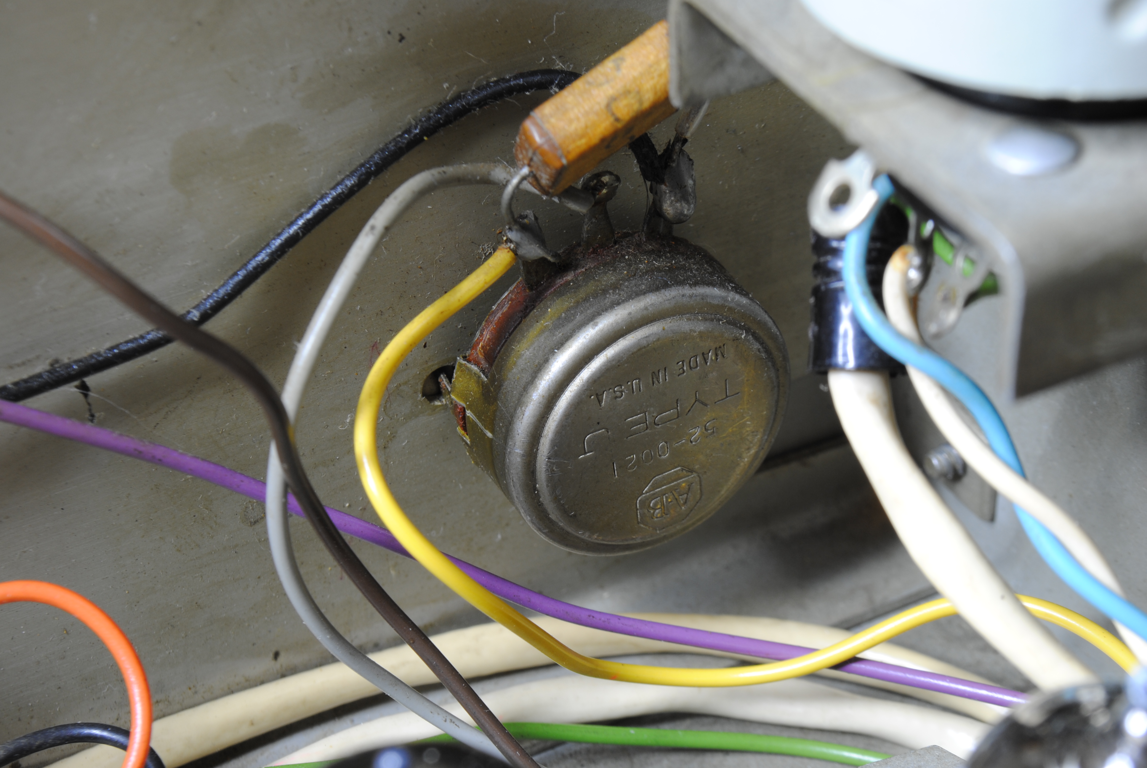
Cotton swabs and Caig DeoxIT® did the job nicely, removing 60-plus years of dirt and nicotine (yuk!) from the contacts. Other than the muck I removed, the pots were in good shape. Ditto for the front-panel switches, which were easily cleaned without need for disassembly.
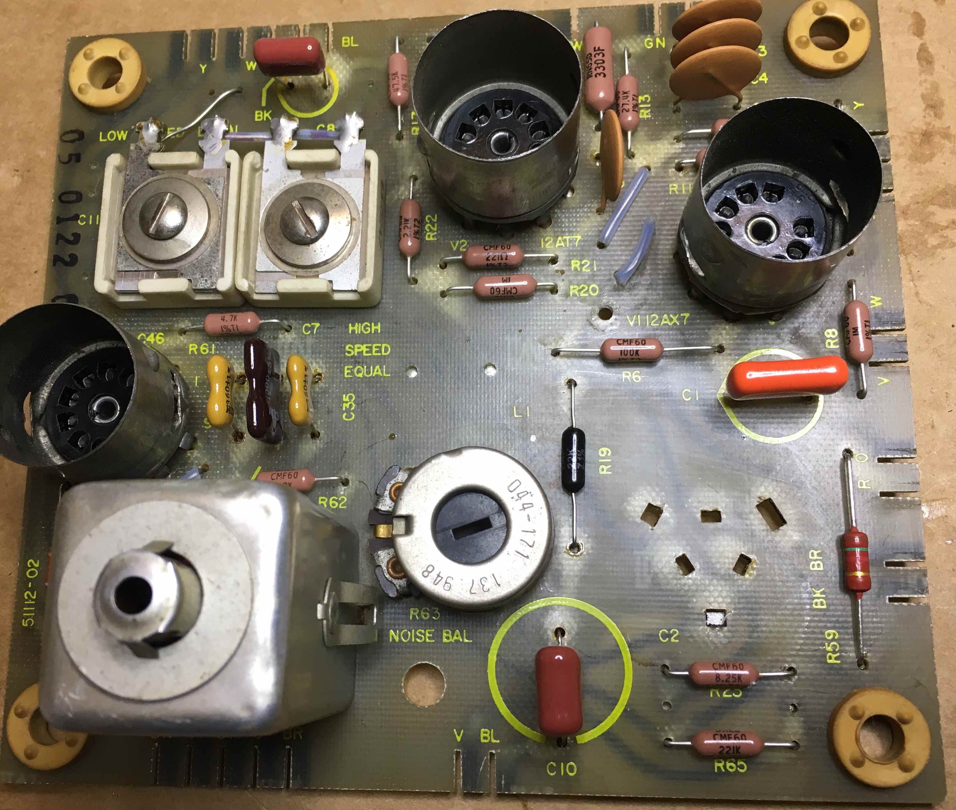
The next part of the plan (or so I thought) was to rebuild the original record and repro PCBs using new, high-quality, tight-tolerance components. Starting with the record PCB, I removed all of the push-on blade connectors, pulled the PCB and de-soldered the old components with the exception of the transformer, the noise balance pot and the two variable capacitors. These last few components would be difficult (if not impossible) to replace and would be retained.
None of the component values were anything extraordinary, so sourcing parts was fairly easy with one notable exception: another of those pesky multi-section capacitors that would be about as easy to find as a hen’s tooth. My solution was to use three individual capacitors with the requisite values and tie their negative sides together at one common point. It wasn’t as elegant as I had hoped, but it was secure and the values were accurate.
And then came the pain. Reinstalling the record PCB required laying it in position at the bottom of the chassis and reattaching the blade connectors. As I started to slide these into position on the PCB, some of them cracked. They were old and brittle and I had little confidence in their ability to survive. There was only one thing to do: leave the whole mess on the workbench and go to Pino’s for a slice of pizza.
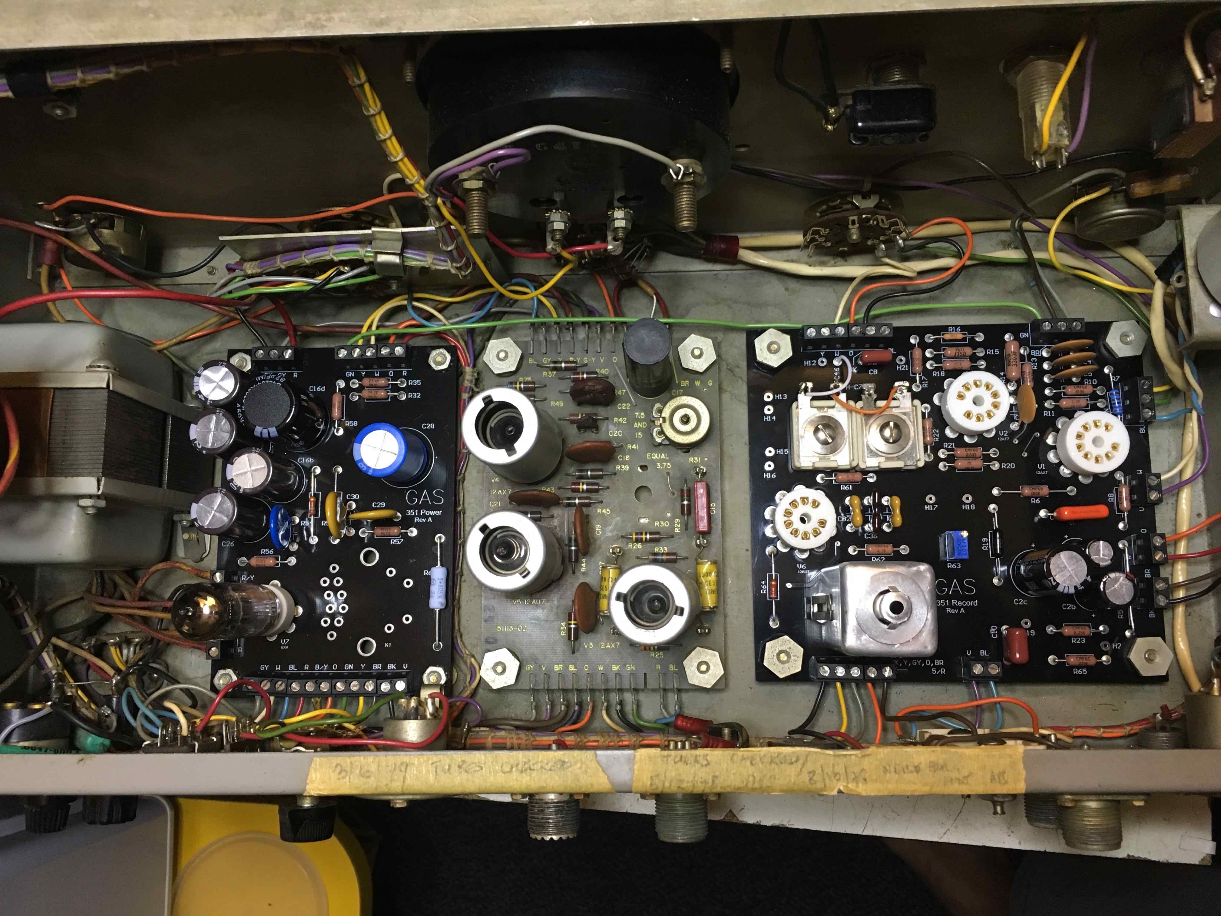
When I returned, I decided that I hadn’t come this far to leave the Dinosaur’s fate in the claws of some old, crappy connectors that hadn’t inspired my confidence even before they started cracking. The smart thing to do would be to purchase new record and repro PCBs from Gas Audio to replace the old PCBs. I was impressed with the quality of the GAS power supply PCB, so I ordered the other two; I placed another order from Mouser for the remaining semiconductors (including a ‘sub for the noise balance pot). Now the only components to be re-used would be the transformer and the two variable capacitors.
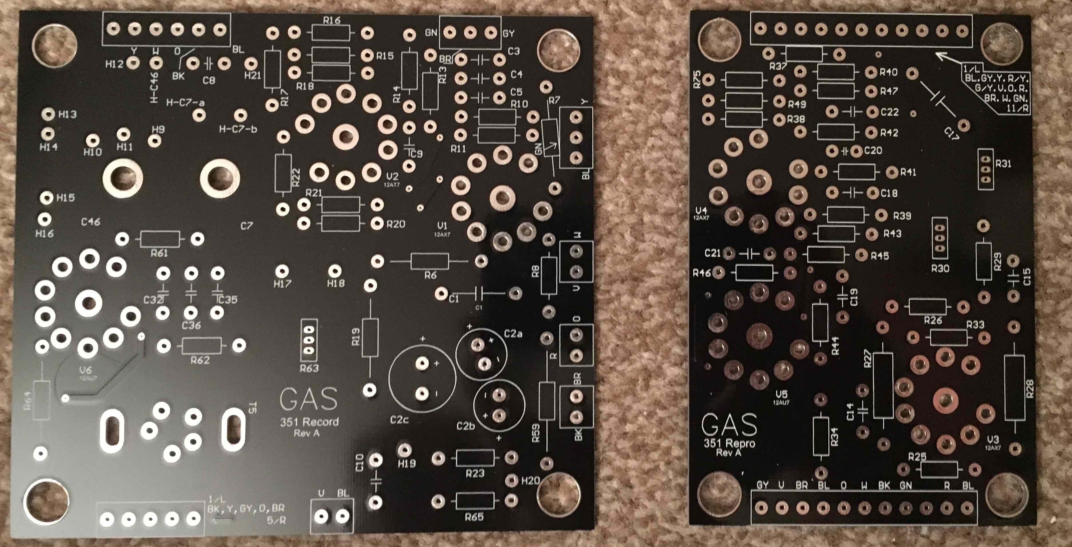
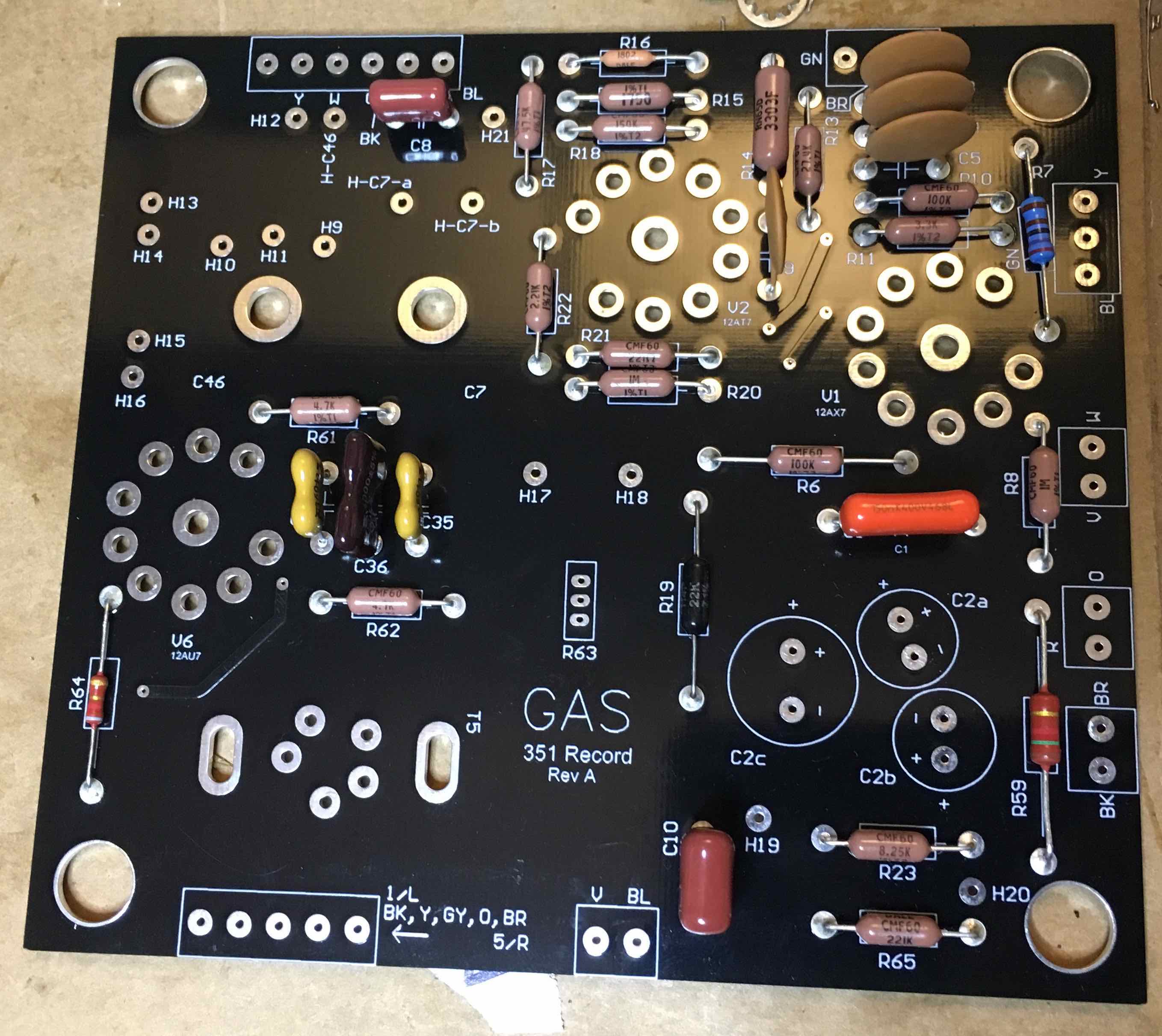
Soldering the components into the new PCB was a joy—the traces on the GAS PCB are neatly arranged and component locations are easily identified. GAS even made space on the PCB for three discrete replacement capacitors that substitute for the multi-section capacitor, so that was no longer an issue.
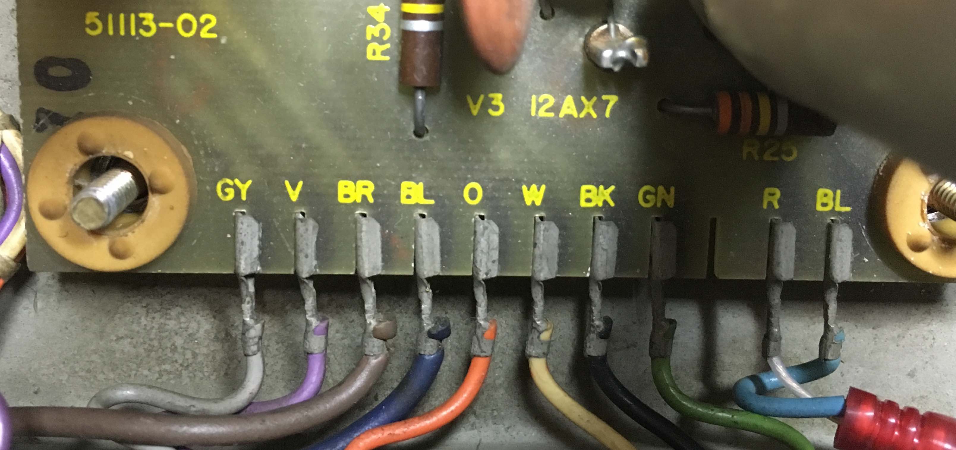
As is the case with the power supply PCB, the GAS record PCB uses terminal blocks to attach the wiring. I was again able to snip off the old push-on connectors, strip the wiring and insert the bare wire into the terminal blocks, providing very secure connections.
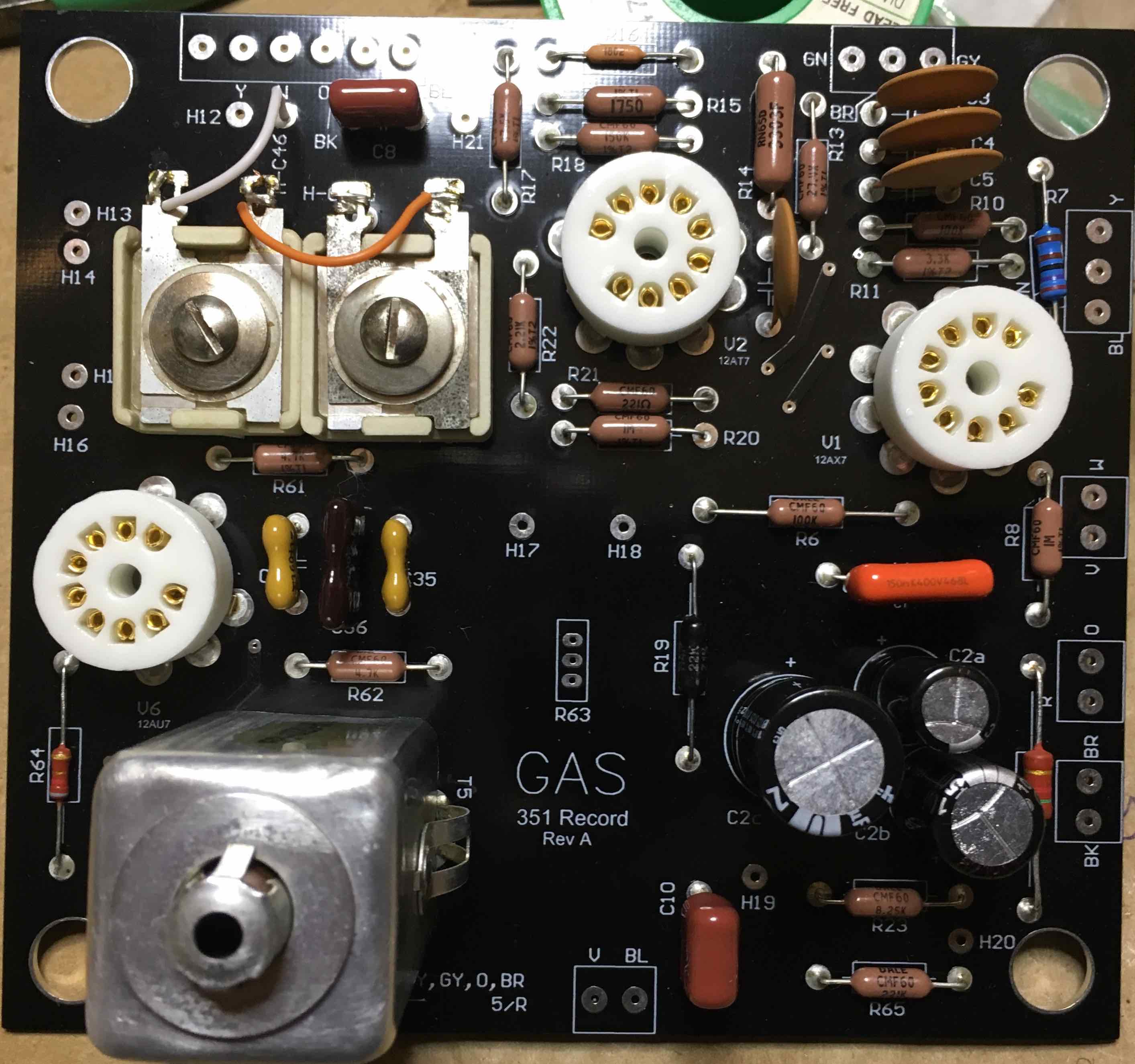
I don’t like the idea of introducing too many variables at the same time, so I decided to test the 351 with the new record PCB before starting work on the repro PCB. I loaded the record PCB with the original tubes, fired it up and tried it. Everything worked, but it was a little bit noisy. Hmmmm….
Next time we’ll look at the replacement repro PCB and talk tubes.