Has it really been three months since we last visited the Ampex 351 Audio Dinosaur? I estimate that I’ve logged 200,000 miles since the last update. Summer has a way of doing that to me. Tour dates fly down the road fast and furious until the calm of the Fall months arrives…
… Except that the calm of Fall didn’t arrive. I still have about 15 shows on the calendar until the end of the year, which is unusual. The total number of shows this year will be around the average of 85, but it seems that we’re backloaded in the fourth quarter, as opposed to the dates having been evenly distributed throughout the year.
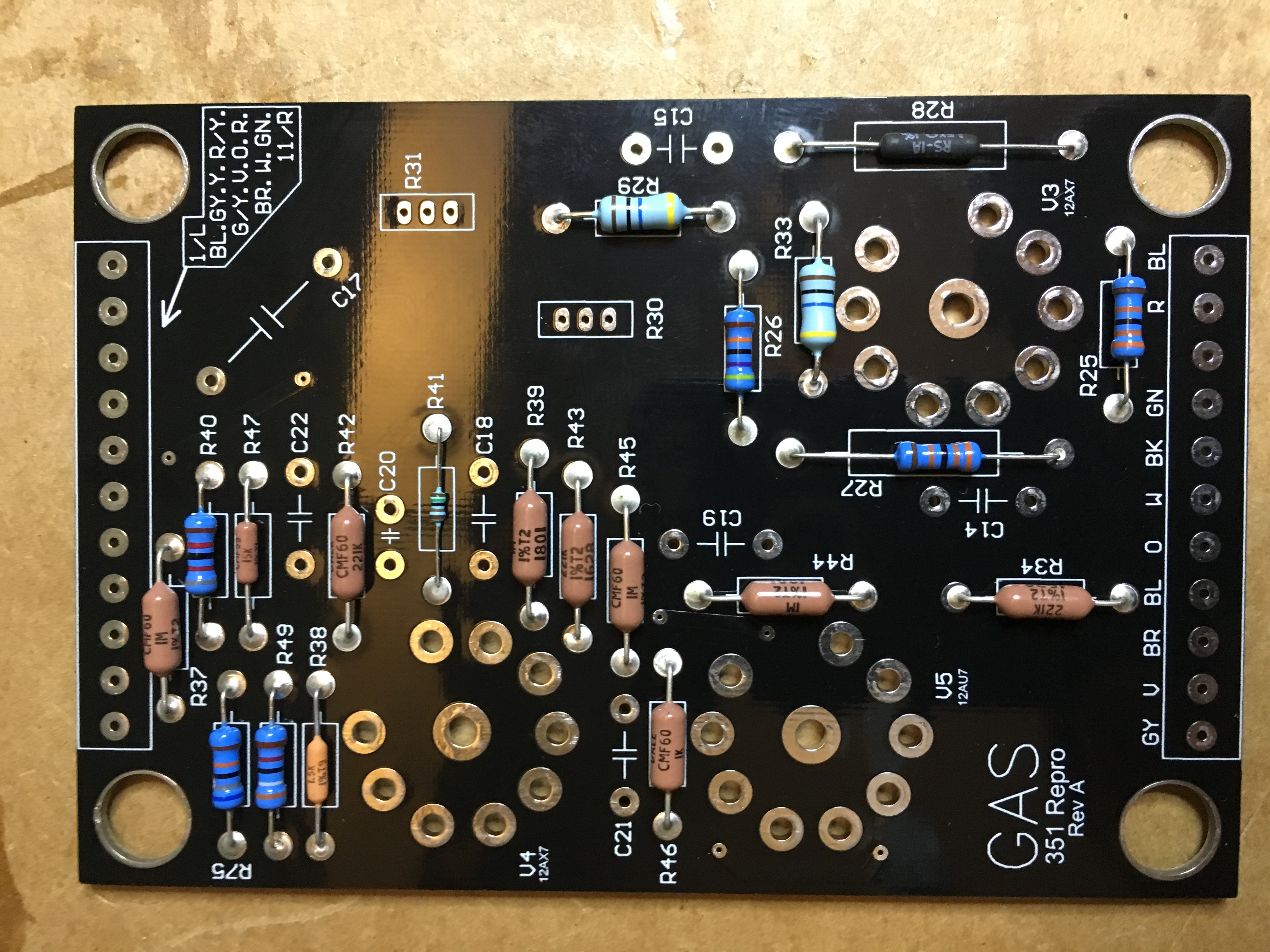
Anyway, back in Resurrection, Part 3, I had replaced the Record PCB, the preamp was working pretty well, and it was time to replace the Repro PCB with a brand spankin’ new one from GAS Recording Equipment. Here’s a photo of the new Repro PCB, partially populated:
And here is the Repro PCB completed:
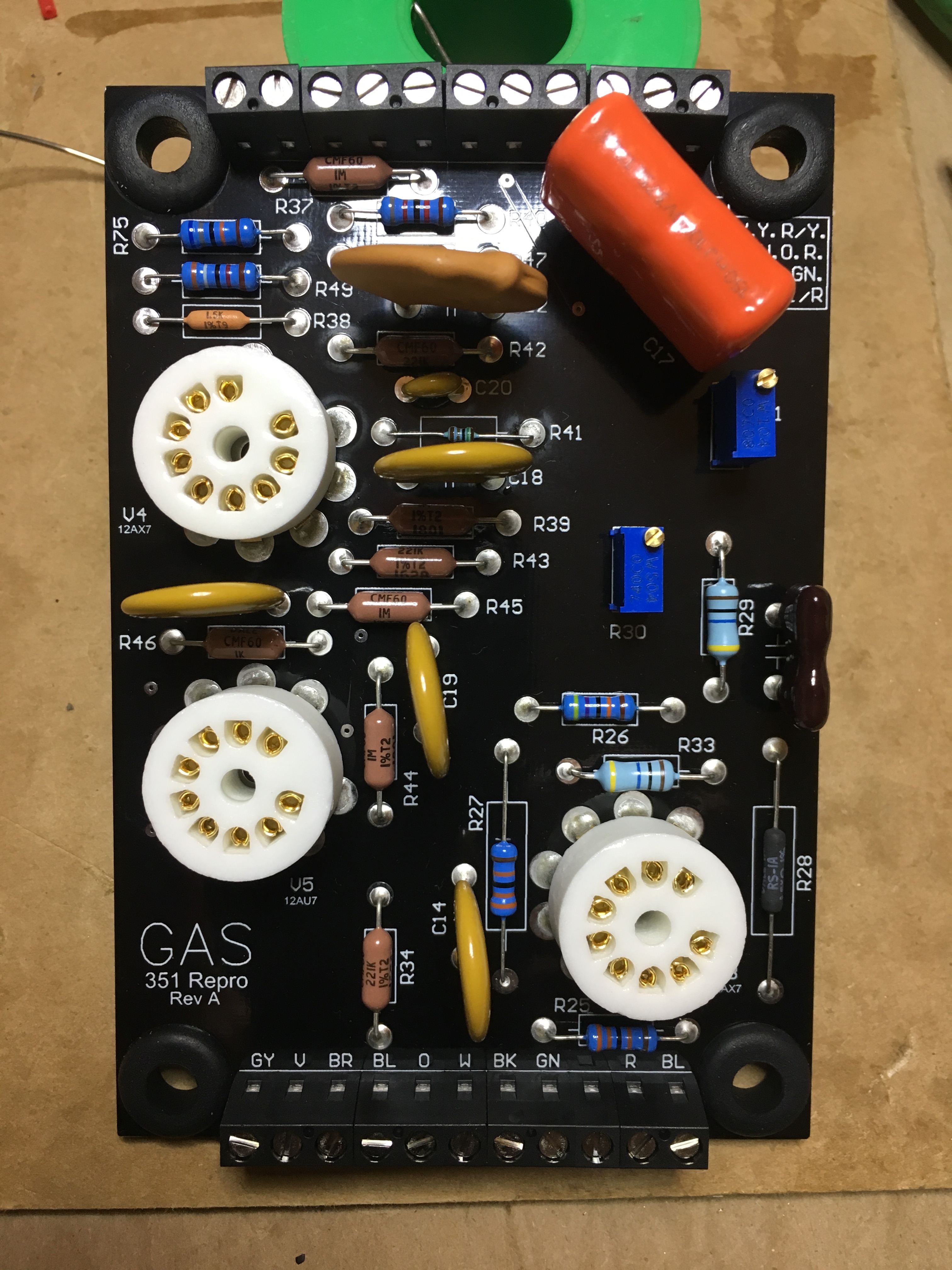
As with the power supply and Record PCBs, my confidence level was high since the new Repro PCB came loaded with high-quality, tight-tolerance components, along with terminal block connectors replacing those unreliable blade connectors.
Here’s a photo of the chassis with all of the new PCBs installed.
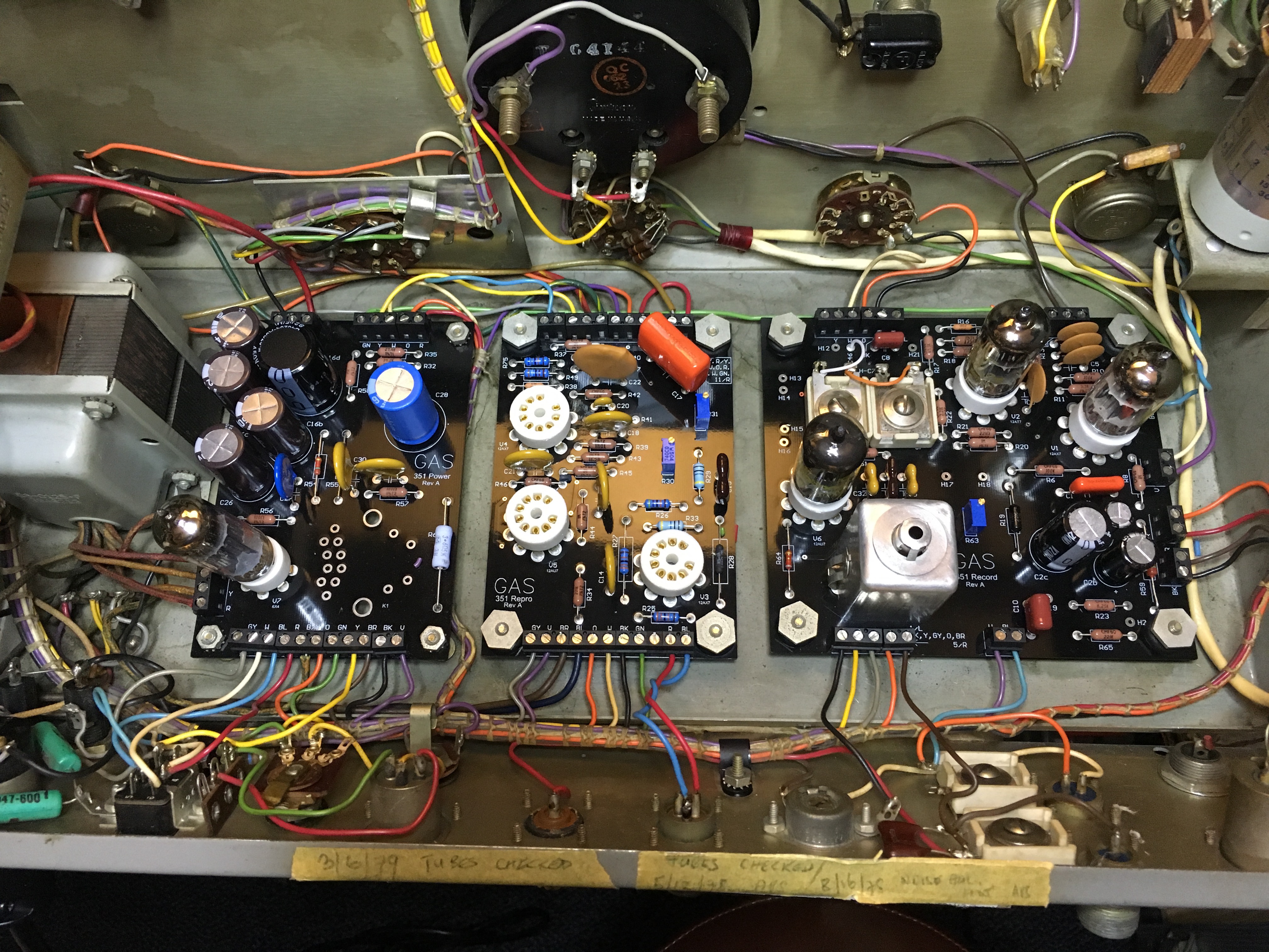
Notice how the front and rear panels pivot out of the way so you can access the wiring, a testament to the unit’s serviceability.
I fired up the 351 and connected a microphone to make sure that everything was still working properly. It was a bit on the noisy side, which could be due to (a) noisy tubes. or (b) lack of shielding, or (c) both.
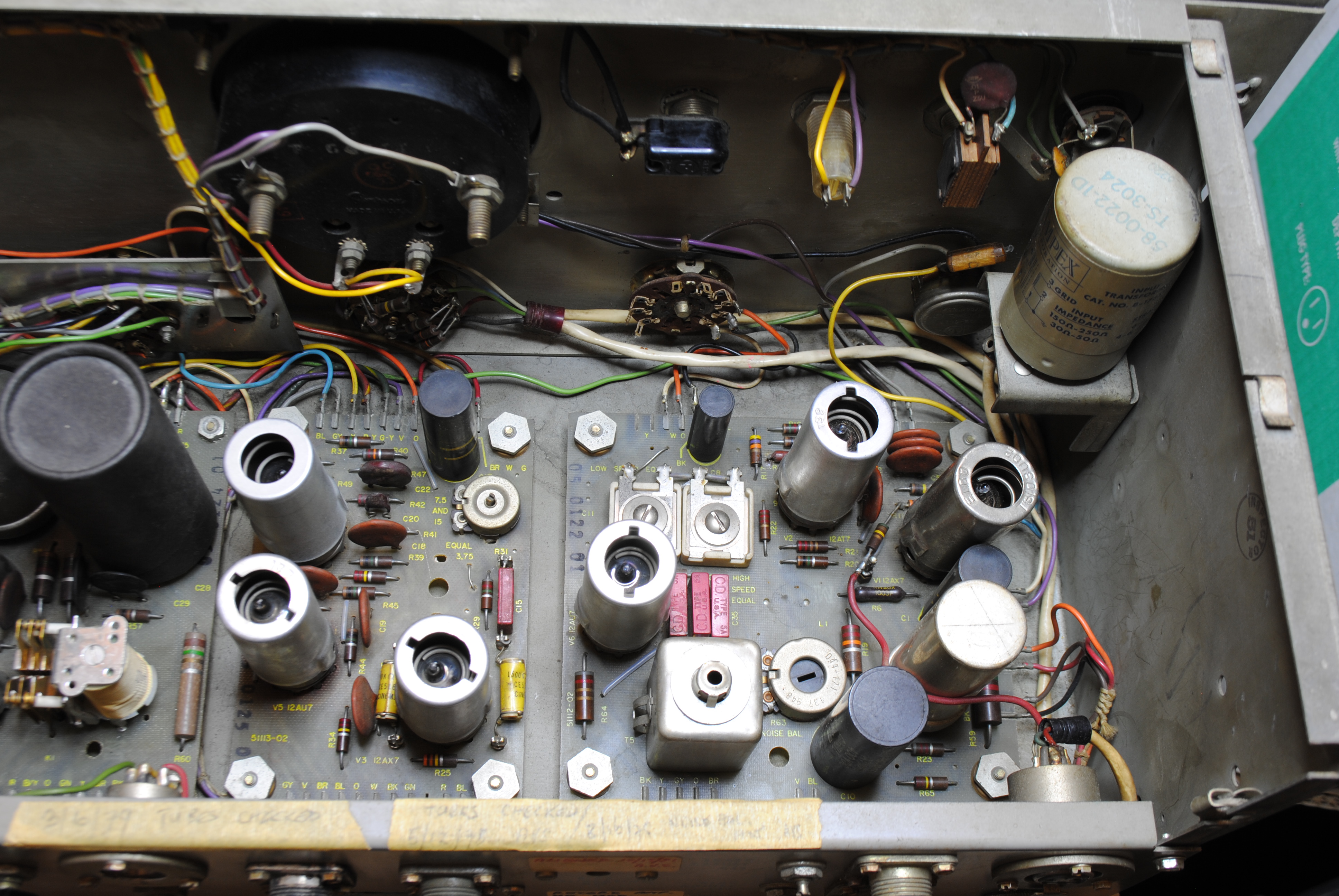
Replacing the old tubes is definitely on the schedule, but I was also aware that there were a couple of important changes from the original design. If you look at the photo below showing the original PCBs, you’ll see that most of the tubes have shields over them. The shields act as heat sinks, but also protect the tubes from RFI. Once these shields are eliminated (as they are using the new PCBs), there’s a greater possibility of RFI causing noise.
I didn’t have the chassis cage cover for the top rear of the unit, which meant not only that another layer of RFI shielding had been removed, but also that there was a possibility of “stuff’”(you know… PBJ sandwiches, goldfish, etc.) being dropped onto the circuit boards—not a great idea where tubes and high voltages are present.
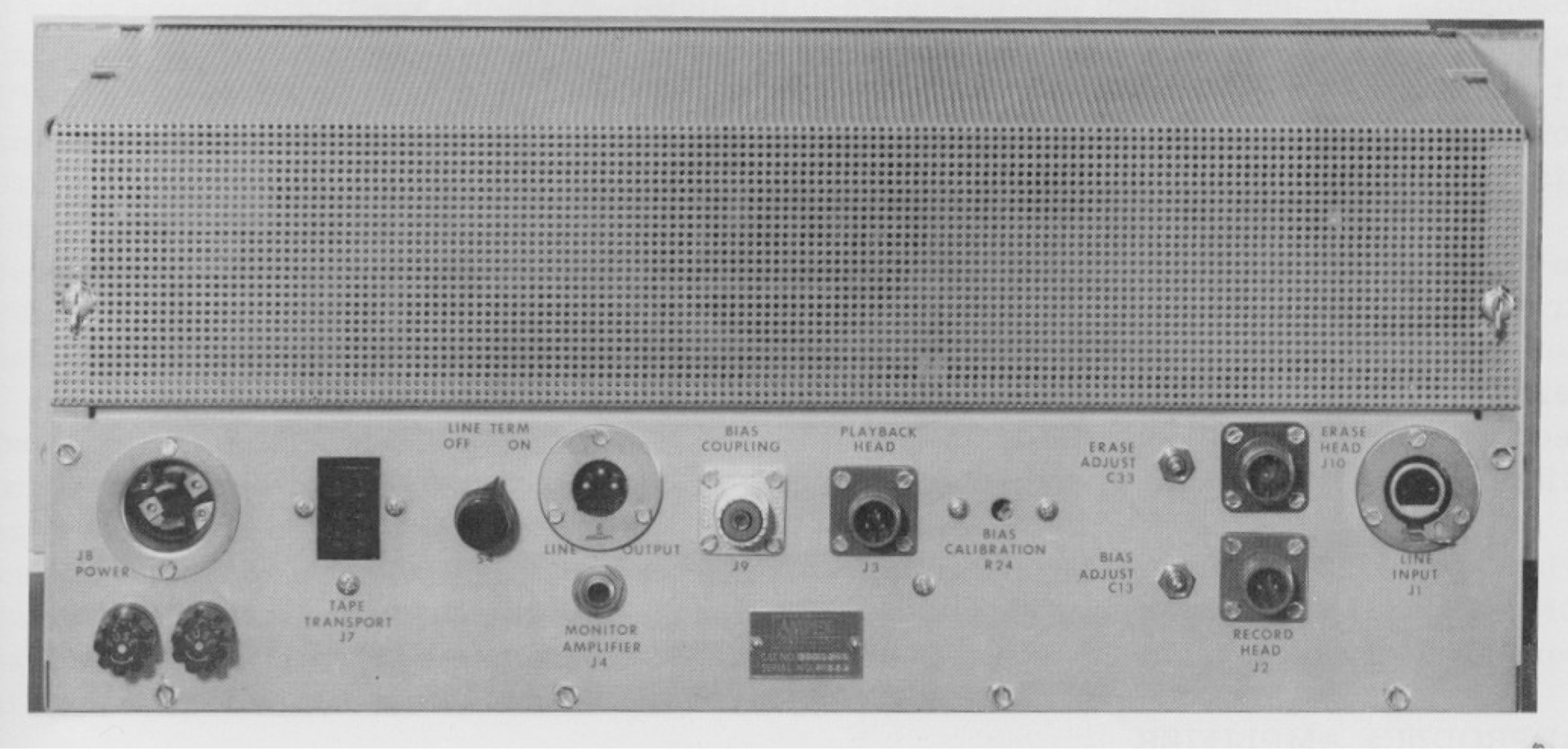
I trolled Fleabay looking for a replacement, but it became evident that this was not going to happen. If anyone had such a part, it’d undoubtedly be part of their own 351. It looked to me like the cover was made from nothing more than perforated steel, so I decided I’d make my own. Additional trolling in the dark corners of the web (okay, I looked on Amazon) yielded a sheet of 22-gauge, galvanized, perforated steel for about 30 bucks.
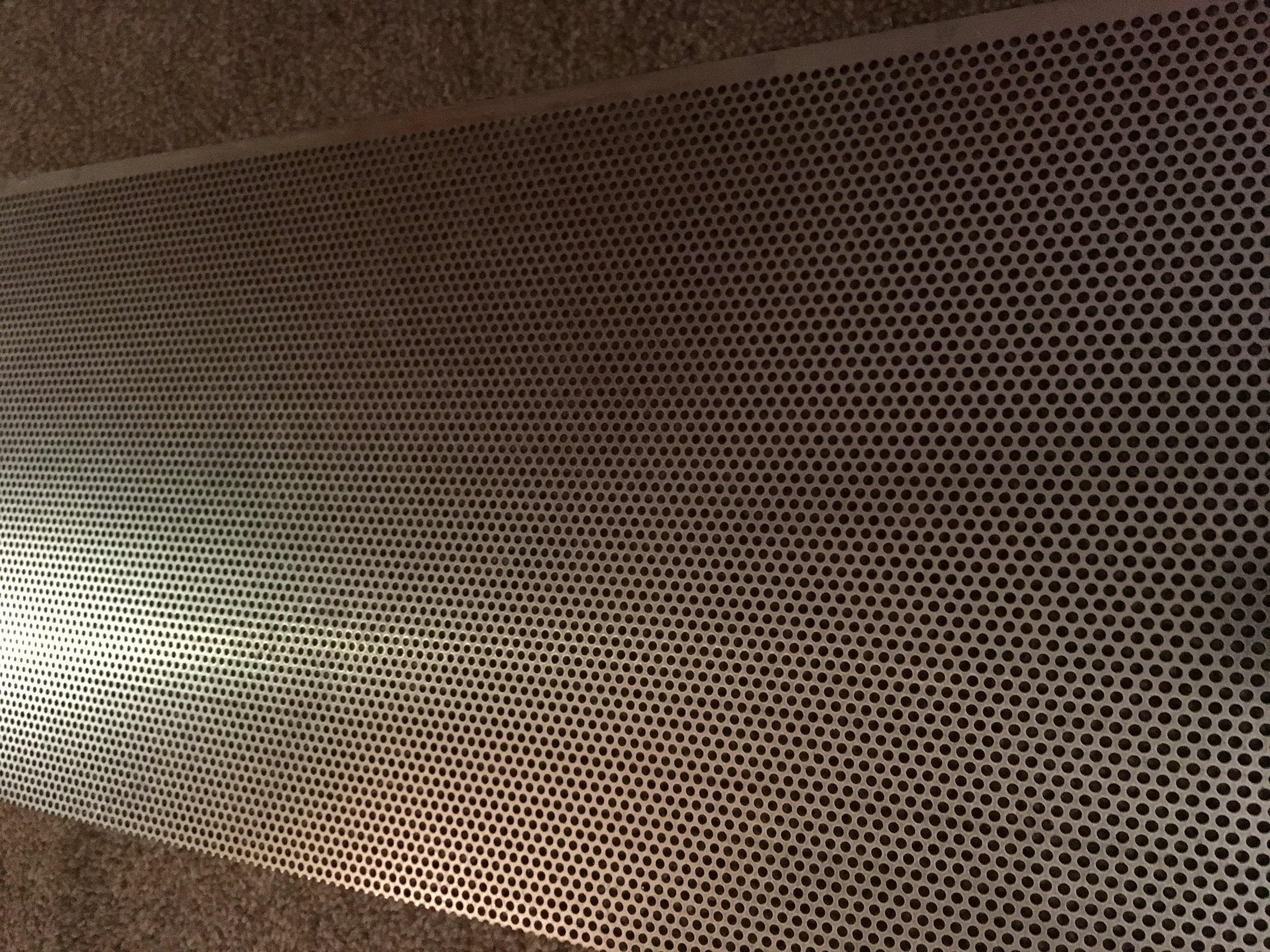
The next trick would be cutting it down to size, bending it into the proper shape, and notching it to accommodate the screws and fastening clips on the chassis. A friend of mine suggested tin snips to do the trimming, but I didn’t love that idea anymore than I liked the idea of using my trusty Dremel tool to cut it to size. I decided to bring the sheet to a local metal shop and have them cut it down. And you know what? They did it in about 10 seconds and wouldn’t take any money from me. Ain’t that sumpin?
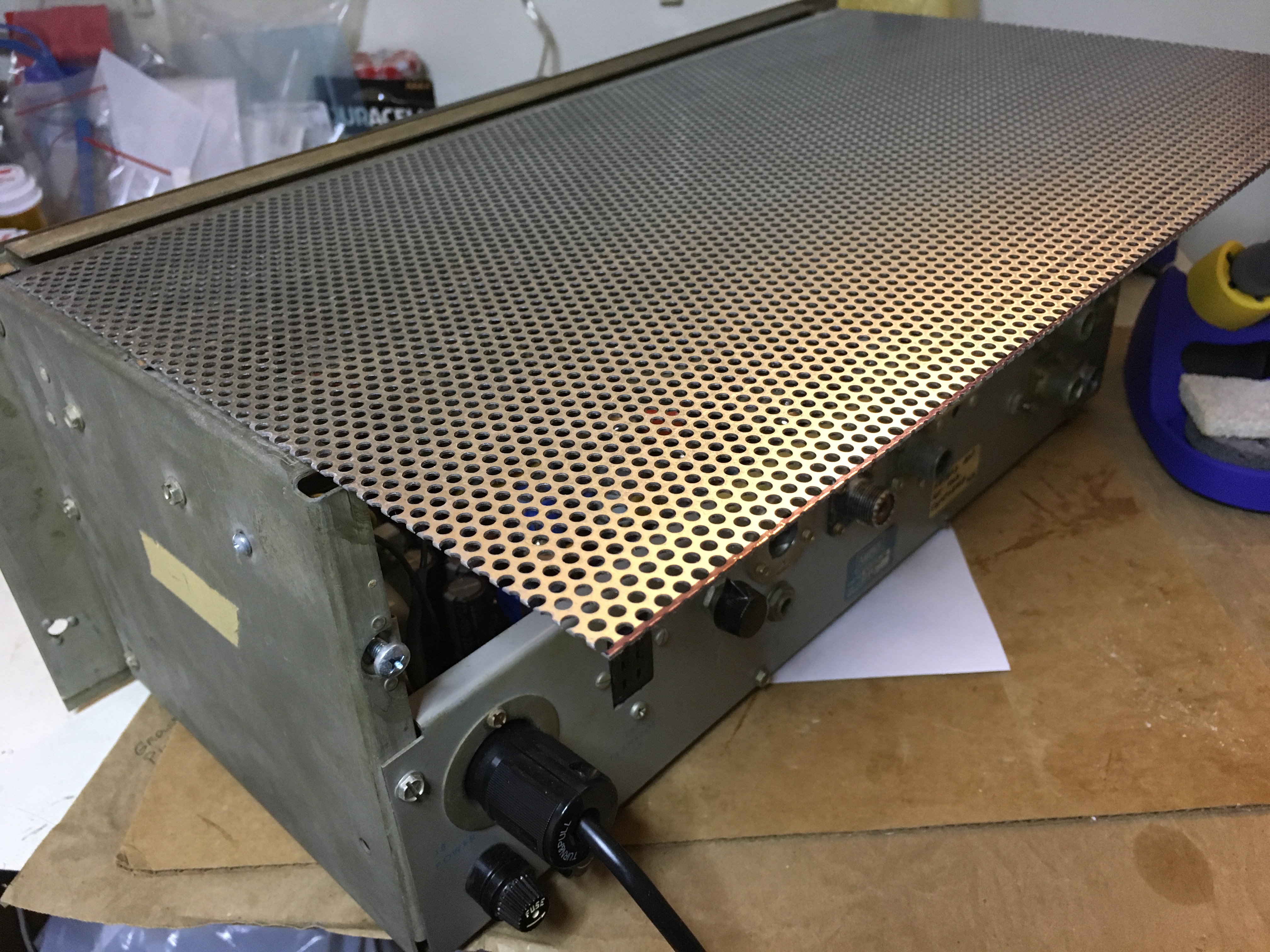
Once I had the sheet cut to the correct size, I clamped it to the edge of a workbench with one 2×4 and used another 2×4 to bend it 90 degrees. Then I used a Dremel to make notches for the chassis clips and screw holes. It worked like a charm. Here’s a photo of the new cover installed onto the chassis:
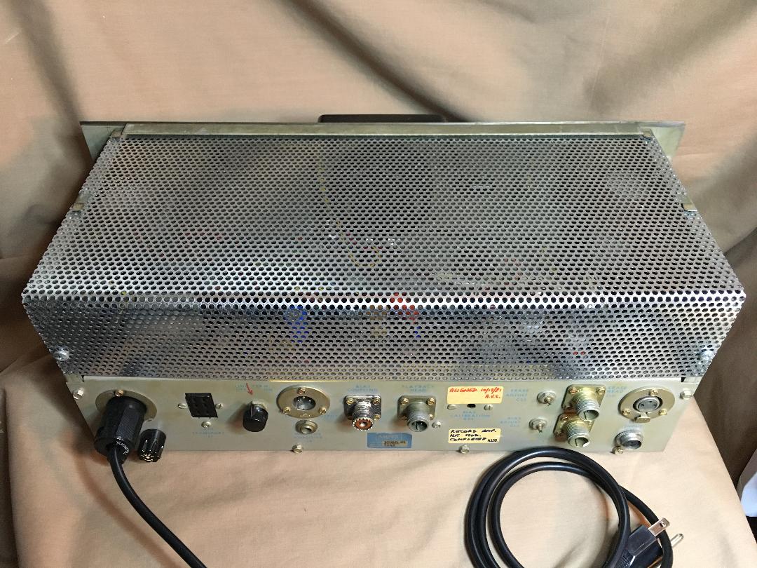
It fit like a glove but it’s way too shiny, so I may have to bury the cover in the front yard for a few weeks to get some dirt on it so that it matches the rest of the metalwork(!)
I now have a safe Audio Dinosaur, with one last step to attend: sorting out the tubes.
Stay tuned!
