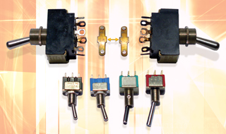
At top, two NOS (new old stock) American-made switches—the silver-plated solder lugs tarnished by time, except on the left—are shown recently polished. Between them are the two rockers from inside the Chinese Vox switches, looking older than their five years. The bottom-left pair are miniature Chinese switches that appear comparable to the higher-quality, silver-plated Japanese and American switches to the lower-right. The differences you can’t see are the contact and housing materials. Chinese switch housings tend to melt when overheated during soldering.
A simple excursion into geek territory can turn into a revelation or three; you might experience profound light-bulb moments or merely the simple reminder of a component not to be taken for granted. The Vox AC30 is a great amp. The preamp section has versatile EQ, reverb and an effects loop. The 30-watt power amp section has interesting features, like a tube rectifier (earlier versions were solid-state), and modern niceties like bias and filter capacitor switches on the rear panel for vintage/modern options.
A few years ago, a famous band came through town with a troubled Chinese-made AC30 guitar amp. In the four hours allowed for a diagnosis, I replaced a broken bias resistor and a suspicious standby switch. The EL84 output tubes were also suspect because they were behaving as though microphonic — a strange, harmonically crunchy resonance when the amp was played loud enough to vibrate them. I had no EL84s in stock but would later learn that they were not the problem, so when another ailing AC30 came in, my curiosity was piqued.
The second AC30 was DOA. I replaced a blown fuse, and in such cases a gentle wake-up call from Mr. Variac is the safest way to bring troubled power amplifiers back from the dead. (Variac is the trade name for a variable-voltage auto-transformer, easily recognizable by its giant knob.) Rather than a traditional “hard-boot,” the Variac’s soft-start lets me look for the warning signs — potentially excessive voltage or current — before damage can occur. For example, visible glass-fuse wires will “flex” during slow power-up; stop in time and they won’t blow. The Variac was barely beyond 75 percent when the 5AR4/GZ34 rectifier tube began arcing. Clearly, something was wrong.
A Web search harvested plenty of info about short-lived 5AR4s. The general consensus is that modern tubes aren’t up to vintage standards, but it’s too easy to blame all of them. Even during the heyday of the Thermionic era, there were loser tubes. I confirmed this with my Uncle Vince and his pals from the early TV era. Sometimes only one particular manufacturer’s version (or production run) would work in certain critical applications, yet all had the same designation. Guitar amp designs — and users — are often abusive, and I profess sympathy for the tubes.
Tube Amp ABCs
A vacuum tube’s gradual warm-up time may give the impression of slow and gentle, but the power transformer and the power switch take the initial hit because a cold tube filament looks more like a short-circuit. (Its resistance goes up when warm.) Tubes take time to “warm up” because their filaments glow reddish-orange instead of the yellow-white of an incandescent light bulb. The orange heat is high enough to burn electrons off the cathode but low enough to ensure longevity. In an all-tube amplifier — one with a rectifier tube and no standby switch — the high voltage (HV) comes up slowly as the rectifier tube warms up. During this temperature transition, the preamp tubes may start out with a rush of noise that settles down eventually — reason enough to leave gear powered up during a session or at live gigs.
Once the filament is hot enough, negatively charged electrons need somewhere to go and the positively charged plate (the large metal structure under the glass) is absolutely irresistible, so the current flows easily. The bias circuit stops the stampede and optimizes current flow. Perhaps due to random noises, the standby switch was invented. This ultimate mute switch interrupts the HV power supply — aka, the B+ — leaving the aroused electrons with nowhere to go.
However, designers have not been consistent about how standby switches are wired. On this recent AC30, the switch is between the HV center-tap and ground. Other versions relocate the switch after the rectifier and filter capacitors. If the rectifier tube is already warmed up, a switch at the center tap sees the initial stress of charging a capacitor quickly. The post-rectifier standby switch lets the filter capacitors charge up to a higher-than-normal voltage, because without the power amp, there is no load. In this application, the voltage must be within 70 percent of the cap’s voltage rating or the overcharging could potentially shorten the cap’s life. When in standby, one solution is to simulate the power amp load with resistors. A third option is rewiring the standby switch in series with the rectifier’s filament so that the HV slowly turns on (or off). This is kinder to the tubes, transformer and capacitors.
One Last Check
The AC30 is hardly technician-friendly: It’s not easy to audition tubes or gain access to the electronics without pulling the entire chassis out of the cab. So before my assistant reloaded the chassis into the cabinet, we did one last test, only to hear a strange buzz from the power transformer, as if it were intermittently shorted.
After the amp sat idle for a week or two, the lack of exercise and self-cleaning increased the switch’s contact resistance. A new switch fixed the final problem and I disassembled the old ones to see why they were failing. On the inside, both switches were Double-Pole/Double-Throw (DPDT) types with six contacts, but on the outside, only four contacts are “available,” making this strictly an on/off switch rather than the optional on/on. Inside the switch are two brass “paddles,” one for each pole (circuit). Riveted to the brass are two silver-ish “buttons” that mate with either of two internal contacts (one unused).
In this case, the “common” (wiper) connection at the pivot point was a poor-quality brass (an amalgam of copper, zinc and a healthy dose of impurities). The lack of quality materials and an environmental seal caused the brass to tarnish. This added resistance at the pivot point, which worsened each time the switch was thrown with the power on. If you’ve ever accidentally plugged something in with the power switch on, the resulting spark is visual proof that circuitry can be “reactive,” the reflected inertia of all the stuff being driven. Inside a switch, sparks from high voltages or currents can become a self-oscillating arc, degrading the switch contacts by depositing carbon until there is more resistance than conductance.
Normally, spring-loaded contacts mate with enough force/impact to make a solid, reliable connection. And if the internal contact pressure/impact or wiping action is sufficient, the switch self-cleans its contacts. By design, switch contacts should have low resistance, which means using (or plating with) high-quality materials (nickel), precious metals (silver) and gold for audio applications.
Eddie thanks Christian Groves and Tom Morrongiello for their Voxes. Visit Eddie atwww.tangible-technology.com.
AUDIO SCIENCE
The most basic passive electrical components, switches, literally make or break a circuit. Mechanical switches come in many forms — including rotary, toggle, slide, lever or pushbutton types — but all are either continuous (like a light switch) or momentary (like a doorbell) styles. These also come in “normally on” or “normally off” versions, depending on whether engaging the switch makes or interrupts the circuit flow. The simplest, most common switch is a SPST (Single-Pole/Single-Throw) type, with one set of contacts that are connected (“on”) or disconnected (“off”). Other variants include the SPDT (Single-Pole/Double-Throw) with a single contact that can connect to two different contacts; and DPDT (Double-Pole/Double-Throw), where two isolated contacts can be routed in two different ways. Some rotary switches are ganged, providing for complex switching — such as SP8T, 4P12T, etc. — from several stacked “wafers” (layers) of contacts, all moved from a single knob.