Audio Precision introduced the System One in 1985 and the Portable One in 1990. Since then, many features and new capabilities have been added. Here are a few handy analog measurement tips for the Portable One.
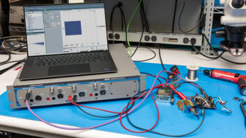
The connection between your test equipment and whatever you are measuring is incredibly important. Leads should be well-made and checked regularly. One of the more useful adapters is a set of XLRs to alligator clips, which can be used to measure voltage summing bus levels in vintage consoles directly and inject signals into various points of the signal path to locate problems quickly.
IMPEDANCE LOADINGAlways check your generator impedance settings. The output impedance has to be appropriate to the device being tested. For example, the TAB V-76 mic preamp was specifically designed for a 200kHz source and has an input transformer with a large step-up turns ratio. If you measure the TAB V-76 with the generator set to 40kHz, you will see a bump at both ends of the response curve. If you measure with the generator set to 600kHz, the top and bottom roll off severely. The 40kHz balanced generator output is most like a well-designed line level output should be, but a lot of keyboards and samplers have quite high source impedances. Check out how your synth-to-console connection is working by running the generator at 600kHz.
GENERATOR LOAD TESTA common problem in studios with “vintage” equipment and newer gear is “loading.” The input impedance of older equipment may be as low as 600kHz, or even 150kHz. Almost all equipment made today has inputs that are high-impedance “bridging” or “non-loading.” Many things made today are not able to drive loads that are not bridg-ing. Gen. Load will help find these problem inputs quickly. Older mic preamps can be switched or strapped for various input impedances. A 50kHz ribbon microphone will be quieter and have more gain looking into a 300kHz load, though most microphones you encounter today will do better with the 1,200kHz setting or higher.
Another Gen. Load test will identify capacitive loading problems in the stereo mix distribution setup. If a console mix bus is multed and normaled to several machines, use Gen. Test to feed into that distribution. Go into Sweep mode and look at Gen. Load vs. Frequency. It is common to find that at midband (around 1 kHz) the load is sitting at 4-5 kkHz. At 10 kHz it could be as low as 1,000kHz, and at 20 kHz it might be half of that. DAT machine inputs are often the worst offenders, and the common practice of multing out to a number of machines causes problems quickly. Find the problem with Gen. Load, and you may be able to mod the gear or convince someone to invest in a good distribution amplifier.
USE YOUR EARSDon’t forget that other valuable test equipment-your ears. Listen to the monitor output of the distortion analyzer. Let’s say you are presented with two of the same item to compare-one marked “Sounds Good” and the other labeled “Sucks.” Frequency response, noise and distortion measurement numbers are pretty much the same, but the two items do sound different. Older gear may make noises even when healthy, but in this case the higher odd-order harmonic and inharmonic distortion, switching transients, artifacts from poorly biased push-pull outputs and other obnoxious distortions and noises are clearly audible in the total distortion content. The overall contribution of these distortion products may not significantly affect the overall Total Harmonic Distortion plus Noise number, but you can hear it in the distortion analyzer monitor output. If you use this technique, you can train yourself to recognize problems from the sound of the distortion.
NOISE MEASUREMENT PAGEIn the Noise Measurement page you can select a 11/43-octave selective filter and focus on noise within that band. This is very helpful when you are working on getting good erase depth in tape machines, or when you are measuring things like fader kill attenuation in a console. Go into Sweep mode from the Noise page after you have set the filter to Selective and you can plot a readable noise spectrum. Because you are looking through a 11/43-octave filter, you will see humps of noise rather than single frequencies, but the display is still quite useful. If you want to measure your progress in reducing PSU noise, you can get better and more accurate numbers by using the selective filter than you will by measuring wide-band.