
There are preamps for every purpose and budget, some with “color” and some transparent. And while some designs may have similar origins, the fact is that a mic preamp can be built from tubes, transistors and ICs, with or without transformers, plus options like built-in converters, DSP, USB and FireWire. With that in mind, let’s pop the hood and explore the options.
THEORY OF RELATIVITY
Preamps need a wide range of gain to accommodate signal levels. Ribbon mics need the most gain, dynamics a little less and condenser mics need the least of all. Capturing a potentially small signal requires a low-source (output) impedance of 50 to 200 ohms, as well as sufficient current to drive a long cable and still arrive at the destination with more signal than noise. Impedance is resistance with a (frequency-sensitive) resonance component. The microphone expects to see a load 10 times its output impedance; not quite a “match” in a technical sense, but the goal is to preserve the signal’s level and integrity.
Tubes, transistors and op amps are active devices that can make gain happen. Voltage gain can also be passively accomplished via an input transformer — with the trade-off of decreased current. A transformer comprises two coils of wire: primary and secondary. Each coil has a number of “turns” (wire wrapped around an “iron” core). The two sets of wires don’t make an electrical connection, and yet the signal still passes between them. Science is cool!
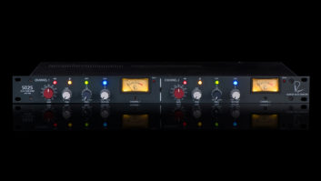
UA SOLO 610 has a switchable HP filter.
In a tube preamp, it’s necessary to match the mic’s native low impedance (lo-Z) to the vacuum tube’s higher voltage level and very hi-Z high impedance (in the meg-ohm range). At the preamp input, the transformer steps up the impedance and the signal level by a ratio that is physically accomplished by the number of turns. The ratio is dependent upon, and determined by, various characteristics of the active circuitry that follows. Optimizing the transformer’s ratio will minimize the noise. For example, the ratio can range from 1:2 (for the Analog Devices AD797 op amp) and up to 1:10 (for vacuum tubes). Beyond 1:10, the performance suffers, with the trade-off being a highly colored signal.
IN THE LOOP
The source of voltage gain can be a single tube or transistor. Devices are daisy-chained for more gain, the target being as high as 70 dB. Each voltage gain stage has a side effect of reversing the signal polarity. Once there is more gain than needed, a portion of the output signal can be mixed with the input signal in a process called negative feedback. This reduces gain with the added benefit of lowering distortion, improving bandwidth, raising the input impedance and lowering the output impedance. The more negative feedback, the less color a circuit will have.
Knowing how your gear behaves can help you get more from it. To “interrogate,” apply a sine wave to the input and increase the gain while either monitoring on a ‘scope or capturing on a workstation. Make sure it is the preamp that’s overloading and not the destination (converter). Negative feedback circuits are less forgiving when overdriven and clip hard, while circuits without feedback can have a smoother transition before running out of headroom. Many vacuum tube output stages, such as preamps by Manley and D.W. Fearn, will overload differently when driving a bridging, hi-Z input vs. a lo-Z, 600-ohm device. That “difference” can be a color option.
VACUUM TUBE OR SOLID-STATE?
The answer might not be what you’d expect. It is possible for solid-state to emulate the Thermionic, simply by keeping the circuit simple and minimizing the feedback. The Neve 1066/1073 preamp and its clones (like the Great River) is a simple circuit made “clever” by its single-knob gain control: a rotary switch. There are three gain stages, the last of which is also the output amplifier. The input transformer and the first stage provide the initial voltage gain. As more gain is needed, the gain switch routes the output from the first stage into the second stage. The gain of each stage is tweaked along the way so each step is in 5dB increments.
Lacking an obvious pad, input attenuation is accomplished on the secondary side of the transformer and integrated into the gain switch. More often than not, the input pad, when user-accessible, is typically on the primary (mic) side of the transformer. The Neve transformer can obviously take the level because it doesn’t need an input pad.
AC/DC
Most of the time, we are only concerned with amplifying alternating current (AC) audio signals. But a circuit that amplifies beyond the subsonic and into the realm of direct current (DC) is called an operational amplifier or op amp. (Übergeeks, please don’t be offended by this oversimplification.) Op amps were originally designed to perform arithmetic operations — part of an analog computer, hence their inherent need to be linear. Op amps, in both discrete and IC form, have the potential to be the least colored (vintage IC op amps being excused from the competition).
Ever wonder why a mic gain pot makes a noisy thump when turned past 75-percent rotation (about the 2 o’clock position)? Most op amps are bipolar-powered — they run on ±15 to 20 volts DC — so that the inputs and the output live right in the middle at a virtual zero volts. Large amounts of AC gain also increase the DC gain, nudging what was virtual zero into the micro- and milli-volt “error” range, creating what is called a DC offset.
DC on a switch or gain pot can make either sound “dirty” when engaged or rotated. Better op amp — based preamps (discrete or IC) include a DC servo. This is a circuit that isolates the signal’s DC component and mixes it back into the preamp — out-of-phase — so that it will cancel or self-correct the problem. If, for example, a +1-volt offset is at the output of the preamp, then applying it to the negative feedback node (the inverting input of an op amp) would produce a -1-volt offset at the output: 1 + (-1) = 0. The John Hardy MPC-1 is one example of this implementation.
HEAD OF THE CLASS
Tube preamps are mostly Class-A, as are many solid-state preamps, such as those from Crane Song and Avalon. There are two types of Class-A: single-device a lá Neve 1066/1073 and dual-device. Class-A means that the active device(s) are “on” and working through 100 percent of the signal cycle. Class-A/B, also dual-device, is more efficient, because each device does a little more than half the work.
The “issue” people have with Class-A/B is the potential for what can happen at the zero crossover point: One device shuts off as the other comes on. It’s a low-level crossfade. Class-A is more popular among purists because there’s no crossover distortion. Circuitry that is biased Class-A runs hotter than your garden-variety chili pepper, so pay attention to ventilation.
TRANSFORMER OR IRON-FREE
Transformerless preamps have existed since the mid-’70s, back when transformers were being singled out (and removed) for detracting from the signal. For both transformers and transformerless (as well as digital technology), considerable design and component improvements have taken place since then. While there are some excellent transformers, generally speaking, transformerless preamps have the potential to be more transparent. Let’s just say there’s a preamp for everyone.
There are plenty of transformer-free, op amp — based preamps in affordable consoles and interfaces. They’re okay if you don’t ask them to work too hard, but rotate the gain past 75-percent rotation and performance will diminish. The obvious solution is to own multiflavor preamps to tackle any job. If you have a gain-challenged preamp, then compensate by using hotter mics or sources that are particularly hot (drums, guitars, screaming vocalists).
Both color and transparency have their place. Transparency is like the truth. Sometimes it’s so revealing it can hurt, but what doesn’t kill us makes us strive to understand and make things better.
Eddie Ciletti is Mix’s “Tech’s Files” columnist.
NEW MIC PREAMPS, AT A GLANCE
Here’s a look at nearly 50 new mic preamplifiers that have debuted or begun shipping in the past year. This chart focuses mainly on studio preamps rather than systems built into digital snakes, stage boxes for consoles and the many DAW front ends with built-in preamps, such as units from MOTU, Lexicon, Digidesign, TC Electronic, M-Audio and others. Also, unless otherwise noted, all include 48VDC phantom powering, input pads and polarity-reverse switches.
Click here for a pdf of the “New Mic Preamps at a Glance” chart.
Microphone Preamplifier Technology
EE: Any audio signal that comprises three electrical components (voltage, current and impedance). The combination yields the signal’s power (or lack of same). Even though you might not think of a mic signal as having “power,” it does in the order of nanowatts (10 with a -9 exponent) as compared to line-level’s milliwatts (10 with a -3 exponent).
In electronics, voltage “times” current (in amps) “equals” power (in watts) (V * I = P), and with the exception of minor losses—nothing is 100-percent efficient—the power on either side of the transformer—primary and secondary—will be nearly the same. So, again, the side effect of passively stepping up the voltage is a decrease in current, which is okay once the signal is safely inside the preamp.
IRON
Signals are “balanced” (in terms of source/output impedance) and differentially modulated (two identical signals of opposite polarity) to maximize the Common Mode (Noise) Rejection Ratio (CMRR). Transformers do this best, and when used as intended, a transformer is your sonically transparent friend.
Modern transformers can deliver either sonic transparency or modest amounts of “color.” For example, the “core” material in a transformer is not pure iron but laminations (a metal sandwich) that is an alloy of various materials—treated steel, “high nickel” and cobalt being cleaner than an iron, nickel and cobalt alloy.
When hit with a hot enough signal and by not using the input pad (if applicable), transformer abuse can simulate the saturated “phat” of analog tape, but only if the gain downstream can be set low enough to avoid clipping.
WATCH YOUR STEP
Voltage gain is easy to grasp, but current gain is another matter. The last (output) stage of any audio device is typically not a voltage gain stage but a “power amp,” a current gain stage that makes the signal stronger—not louder—so it can travel to the outside world with minimal damage.
A tough-to-grasp concept, passive current gain (via transformer) is like downshifting: The vehicle doesn’t go as fast, but it is capable of going up a hill. From stop, you wouldn’t attempt to start in fourth gear. In a tube or solid-state circuit, active current gain is accomplished by first converting the impedance from high to medium (or medium to low) using a cathode (or emitter) follower circuit. Unlike passive conversion, the voltage remains the same while the current and power increase.
Many vacuum tube preamps require a step down-style output transformer to complete the impedance conversion—from medium to low (600 ohms)—balancing the signal in the process. By contrast, some discrete solid-state preamps have such low-output impedance that they can afford to use a step-up transformer and buy a little voltage gain in the process. Neve uses a transformer with a 1:2 ratio that doubles the voltage, a 6dB increase; API’s output transformer ratio is 1:3.
-Eddie Cilettia